|
In
Part II of this series of articles on
the design and construction of the sharpie skiff, Nemah,
I detailed how various structural "sub-assemblies"
can be combined to produce a boat that is both strong and
lightweight. Here in Part III, we will consider plywood
composite bonding techniques, and then go through the actual
process of fabricating a plywood "shell" for Nemah.
Plywood Composite
Variations
There area variety of plywood boat construction systems
that utilize fiberglass tape-bonded joints* Some are actually
plywood "plank on frame" structures that utilize
taped seam joints to eliminate the tricky bevels of chine
logs or seam battens, but are otherwise made up of frames
and other structural members. At the opposite end of the
spectrum are hulls that could be classified as "cold
molded structures fabricated from pro-bonded sheet stock,"
the difference being the degree to which the designer has
relied on the plywood shell itself to cany the structural
loads of the finished boat. Neinah falls near this end of
the design spectrum, while the smaller Constant Camber structures
carry the concept to its logical conclusion.
Bonding Techniques
The goal of any bonding
process is to create a joint that duplicates the structural
characteristics of the materials to be joined. In the case
of plywood composite structures, we want to design a joint
that is as stiff and as strong as the plywood, but is not
so stiff that it would cause the plywood to fail near the
joint by concentrating all the bending loads at one point.
To accomplish this, we will utilize two materials: epoxy
saturated fiberglass tape which supplies the needed tensile
strength; and a fillet of epoxy, wood flour, and colodial
silica which supplies compressive strength as it forms a
radius on the inside of the joint to which the fiberglass
tape will be bonded.
Figure 1- Section Through Chine
In this type of construction,
if the inside and outside layers of fiberglass tape are
not held far enough apart, or if the inside or outside radiuses
of the joint are too small, the fiberglass tape can flex
and fail. A typical plywood composite joint is shown in
Figure 1. Note how the layers of fiberglass tape are feathered
out, reducing the concentration of bending forces.
Fabricating The Shell
As we mentioned in Part
II of this series, Nemah's bottom panel
has it's face grain running across the width of the hull.
This is accomplished by scarphing several 40" x 48"
panels together, edge-to-edge, to form a single sheet long
enough to cut the bottom out of in one piece. The panel
is laid out on both sides of it's centerline at stations
measured from the transom end. This is easily accomplished
using a tape measure and framing square. After the station
points are laid out, the curves are drawn with the aid of
a wood batten stapled directly to the panel face. Cut the
panel out using a jig saw or a circular saw as shown in
Figure 2. (Note: I prefer a wormdrive circular saw, such
as the one shown, which is much more accurate to use, as
they are gyro-stabilized by the blade and armature turning
at right angles to each other.) Plane the edges of the panel
as necessary to smooth the curve to the line.
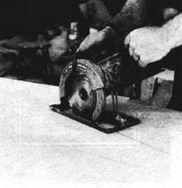 Figure 2
Cutting the Panels to Shape |
Both side panels can be gotten
out of a single 4' x 16' sheet of I /4" marine plywood.
If you are scarphing your side panels out of 4' x 8' sheets,
rip them in half lengthwise and scarph each panel separately,
as it is easier to align a narrower scarph joint for gluing.
The side panels are laid
out along their top edges. (Be sure that the panel edges
you are working from are straight, as they form the sheer
of the boat.) Stations are laid out along the edge of the
panel and lines are squared down to locate the chine line.
Once the layout is complete, with the chine, stem, and transom
end lines drawn in, the two panels are sandwiched and cut
out together.
The transom is assembled
using a solid lumber core, with fore and aft faces of plywood
(or from solid stock with its grain running up and down).
For the prototype, I used 7/8" red cedar for the core,
plywood for the forward face, and tapered strips of mahogany
arranged in a sunburst pattern for the aft face. After the
transom is assembled, it is cut to shape, the side and bottom
cuts being given the specified bevels.
Prior to assembly, all components
should be precoated with epoxy. The side panels and transom
are given three rolled coats on each side. These can be
applied in one operation, moving from panel to panel in
a cycle until they each have received three coats.
Sheathing the inside face
of the bottom panel is done easily. The fiberglass fabric
is spread out while the panel is still dry, and then is
wet out with epoxy, using a squeegee to work the resin into
the fabric. A second coat can be squeegeed on after the
first coat has had a chance to set up a bit A final coat
should be applied by roller, which will finish leveling
the weave of the fabric.
Because the outside of the bottom panel will be sheathed
with fiberglass after the hull is assembled, you don't need
to coat it with epoxy prior to assembling the boat.
Figure 3 Section Through Stem
After the precoated panels
have had a chance to cure for a day (or more, depending
on the weather), you can wash them down with warm water
to remove any wax that may have formed on the resin as it
cured, and then sand the panels. Sanding can be done with
either a random-orbital (DA)
pneumatic sander or an electric orbital sander. If you use
a DA, an 80 grit, c-weight disc works well; if you use an
electric sander, you will want to start with 50 or 60 grit,
followed by 80 or 100 grit. This twostep procedure speeds
the operation, as the 80 or 100 grit paper will load up
quickly if used initially.
Assembling the Shell
Before we "stitch"
the shell together, the lower edge of the bottom panel must
be relieved with a router or block plane as shown in Figure
I, and the inside edges of the side panels need to be beveled
at the stem as shown in Figure 3.
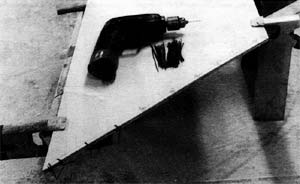
Figure 4
Once the beveling is complete,
we can proceed with the actual "stitching" process,
starting with drilling and wiring the side panels together,
as shown in Figure 4. (Note that the side panels are held
in alignment with clamps during this process.)
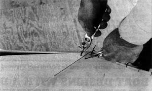
Figure 5
The side panels are now
inverted and spread apart 45 degrees or so. The bottom panel
is placed between the side panels and is supported on boxes
or sawhorses, so that it is easily brought into alignment
with the side panel assembly. The first two wire stitches
are then put in place, as shown in Figure 5. Note how two
pairs of pliers are used to pull the short lengths of waxed
iron tie wire up snug, prior to twisting them tight. After
the ends are given a couple of twists by hand, the stitch
is completed with two or three additional twists using a
pair of Vice-Grip pliers.
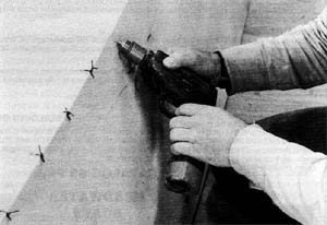
Figure 6
Because of the comparatively
thin plywood used in Nemah, it is possible to drill the
stitching holes through both the side and bottom panels
in a single operation, as shown in Figure 6. Because this
eliminates the need to work from under the shell while installing
the wire ties, the operation proceeds quite quickly.
As stitching progresses
aft (alternately working short portions of both sides),
move the loose end of the bottom panel up or down to bring
it into alignment. Position the last stitches about 2 inches
ahead of the transom end of the hull.
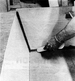
Figure 7
After the stitching operation
is complete, the hull can be righted and placed on low horses.
At this point the temporary spreaders are installed in their
specified positions, as shown in Figure 7. (Note the centerline,
which is marked on the spreader during fabrication.) Once
the spreaders are fitted, adjust the hull on its horses
so that the centerlines of the spreaders are in visual alignment.
The transom can now be bonded
in, being fastened in place with bronze ring nails through
the bottom and side panels. (Note: If the side and bottom
panels do not come out even in length, align the transom
with whichever is shorter, being sure to keep it parallel
with the edge of the longer panel.) After the transom is
in place, a temporary stringer is fitted down one side or
the other of the centerline of the spreaders and attached
to a block screwed to the inside face of the transom. This
stringer can be a long, straight 1x6 or a couple of 5-inch
by 8-foot plywood rippings. If plywood, they can be fitted
to either side of the centerline with one extending forward
and one extending aft. Again sight down the spreader centerline.
If it does not line up with the stem, adjust the positions
of the sawhorses to correct the misalignment.
Applying The Structural
Fillet
The "recipe" I
currently use for structural filleting has proved to be
both economical and easy to work with. It is made up of
one part colodial silica (Cab-o-sil), two to three parts
wood flour, and enough epoxy/hardener mixture to yield a
creamy peanut butter consistency. I start with about 3 ounces
of resin and add the dry ingredients, using a coffee scoop
as a measure. (Larger quantities tend to be hard to mix
evenly and can heat up on you if not used quickly.)
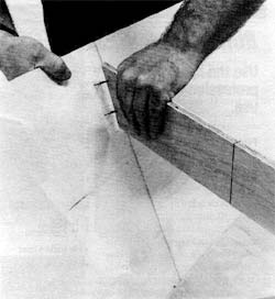
Figure 8
Using a 3/4" x 8"
stir stick, daub the filleting blend into two or three feet
of joint. Then, using a paddle of the proper radius (1/2"
radius for the transom and stem; 1" radius for the
chines), go back over the joint leaving a smooth fillet,
as shown in Figure 8. Remove any excess immediately with
a putty knife, as it is difficult to remove after it cures.
Continue working your way around the perimeter of the boat,
making up additional batches of filleting compound as needed.
You may have to do a little "sculpting" to fill
in at some of the corners.
After the fillet cures,
scrape or sand away any irregularities, using a radiused
block and a piece of coarse sandpaper.
Interior Taping
Because the finished joints
arc to be feathered out, it is a good practice to use a
different width of tape for each layer of the joint. For
Nemah, I used 8.5-ounce tape in 4", 3", and 2"
widths, applying the 4" width first, followed by the
3" and 2" tapes.
Precut your tapes for each
joint; including the chines, the perimeter of the transom
and the inside of the stem; allowing about 2" extra
on each end for lapping in the comers. Just prior to applying
the tape, apply epoxy to the area of the hull where the
tape will contact, paying extra attention to the fillet
itself, which is often porous.
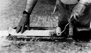
Figure 9
Pre-wet the fiberglass tape
using a roller, as shown in Figure 9. Note how the longer
lengths are rolled up on a short length of broom stick after
wetting out. Figure 10 shows how the tape is applied to
the joint, rolling out a foot or so at a time and smoothing
it out with a gloved hand. All three layers of tape should
be applied in one continuous process, If you should have
to stop, and what has been applied sets up, you will need
to sand any irregularities and then re-wet the joints before
continuing.
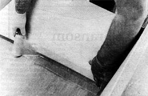
Figure 10
After the interior tape
has set, brush on one or more additional coats of epoxy
to fill the weave of the fabric.
Bonding the Exterior
After the interior bonding
is complete, invert the hull and stabilize it on saw horses.
Clip one side of each of the wires down close to the plywood,
and then ease them out, using a claw hammer.
Using a block plane followed
by a sanding block, radius the chines as shown in Figure
1. Round off the bottom and sides of the transom in a similar
fashion. Take care when radiusing the stem that it remains
straight when viewed from the side. The stem heel should
be well rounded off, as it will receive quite a number of
layers of tape, and could develop a slight bulge.
After lightly sanding the
whole bottom to remove any splinters and so forth, position
the sheathing fabric and smooth it out. Wet out the bottom
sheathing with epoxy, using a squeegee, taking care not
to allow excess resin to run down the sides of the hull.
At this point you have the option of immediately trimming
the fiberglass fabric around the perimeter of the bottom
panel with a sharp utility knife or a single edge razor
blade, and then going ahead with the taping of the outside
pints; or letting the bottom sheathing cure and trimming
it afterward. If you plan to let it cure, you can squeegee
a second coat of resin into the weave as it sets. If you
do trim it after it cures, be sure to sand it to a feather
edge before
applying the outside tape.
Outside taping is essentially
a repeat of the procedure for interior bonding, except that
it is much easier to apply, owing to easier access. As with
the interior, be sure to wet out the edges of the joint
before applying the tape. Apply one or two additional coats
of epoxy to fill the weave.
Allow the tape to cure for
a day or so, and then feather sand as shown in Figure 1.
Use care while sanding to prevent excess removal of material
or sanding through the epoxy coating of the side panels.
(You need not sand the inside tape in the areas where the
fore or aft flotation chambers will be fitted) Take extra
care when sanding in the area of the radius itself: You
may want to hand sand this area to prevent sanding through
the tape. After sanding, apply one last coat of resin to
fill in any irregularities.
Next time, in the final
installment of this series, we will bring Nemah to completion,
trimming her out and fitting her rig.

Visit Tracy's website:
https://www.tracyobrien.com/
|