Through-out the 1950's, most Johnson and Evinrude outboards which utilized remote fuel tanks were furnished with pressurized tanks which did not require a fuel pump. I am not sure why Outboard Marine Corp (OMC) continued to use the pressure tanks long after the other major manufacturer of outboards (Mercury) did away with them. Certainly a fuel pump and non-pressurized tank were a cheaper combination than the special pressure tank with it’s complicated priming pump and over-pressure relief valve and gasketing. Indeed, the third division of OMC, the Gale division, sold lower-priced generic outboards equipped with fuel pumps, and pumps were optional equipment on some of the “flagship”-brand Johnson and Evinrude engines.
 click images to enlarge
 |
There are a couple of issues with the pressure tanks; first, they are no longer made so only used tanks are available. Since the thin steel shells can corrode through rather quickly, it is getting harder to locate good used pressure tanks, and I have noticed that the prices are climbing, especially on the internet auction sites. I should add the internet auction sites are usually lousy places to buy such items, in my opinion, as the prices seem to be especially high and because you can not inspect the tank before buying it. The special “quick-connect” fitting that couples the fuel hose to the outboard is also a rare item that is getting hard to find. The special “twin” hose is still made but not many shops stock it.
The second issue is one of safety; the idea of carrying pressurized containers of gasoline in the boat is just plain scary to a lot of folks, especially those who smoke. Since it is very difficult to get one of these old tanks completely sealed it is not uncommon for them to vent small amounts of gasoline vapors. No big concern in an open boat but a very big concern in a boat with enclosed compartments. And if nothing else, a seeping pressure tank can make a real mess in the boat.
 It is possible to “ditch” the pressure tank and convert these old OMC outboards to use a fuel pump and a standard outboard motor gasoline tank such as those available at any boat dealer and many discount stores. For some models it is especially easy; the 10 hp and 18 hp , for example, featured a fuel pump as standard equipment after about 1960, and if one can find a “junker” engine fitted with the fuel pump, it is a simple matter to transfer the parts to a pressure tank version. A diaphragm pump was used which utilized pressure and vacuum pulsations from the engine crankcase acting on one side of the diaphragm, to pump gasoline on the other side of the diaphragm. The “transfer port” covers were the locations “tapped” for these pressure/ vacuum pulsations. These transfer port covers existed on the earlier pressure tank versions of the engines and were just simple castings that required little factory re-tooling in order to modify them to serve as the source of the pulsations. On the models below about 20 hp, the cover was modified to have a fuel pump mounted directly to it. On models over 20 hp, the cover was either modified to have the pump mounted direct to the cover, or the cover was fitted with a hose barb and the pulsations were conducted to a remote-mounted fuel pump via a hose.
If one can locate the fuel pump, transfer port cover, and the engine-mounted “quick connect” fitting from a fuel-pump-equipped engine, those parts can be transfer to an earlier pressure tank version of the same engine. Once the parts are mounted, the only other task is to plug the hose barb on the intake manifold which formerly supplied the “pressure” for the pressure tank. Although many people use a screw and/or epoxy for this “plugging,” I will suggest that you check-out your local auto parts store for little rubber nipples that are sold to hot-rodders for plugging unused vacuum lines on their modified autos. Clamping one of these nipples on the pressure barb leaves one the option of converting the engine back at some future date.
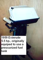
 Unfortunately these conversion pieces can sometimes be difficult to locate. And some engines, such as the 7 ½ hp which was discontinued after 1958, never were available with the fuel pump as standard equipment. Then there is the 5 ½ hp which had a fuel pump after about 1960, but which never have the transfer port covers of the other models. When it was time to convert the 5 ½ to a standard fuel pump, OMC had to change the casting of the cylinder block to provide a mount for the fuel pump.
The purpose of this column is to show how to convert a 5 ½ hp OMC outboard to use a fuel pump, utilizing “off-the-shelf” components that anybody can located without having to frequent the outboard motor flea markets and swap meets. Although this method of conversion is the only option for converting a 5 ½ hp, which lacks the transfer port covers, this method should work equally as well with any pressure tank OMC engine with a fuel burn that does not exceed the capacity of the pump which is a little over 3 gallons per hour. For reference, my 1957 18 hp burns about 2 gallons an hour and an 18 hp or 20 hp engine would be about the biggest I would use this particular pump on. Used OEM parts to convert the larger “Big Twin” OMC’s of 25 hp and up are much easier to find than parts for converting the smaller engines, and I would go that route if converting a Big Twin.
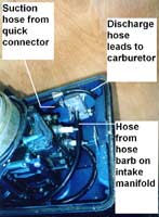
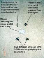 The pump I used on the 5.5 was a Mikuni brand “rectangular” or “square” pump with a single outlet; I could not locate a model number on it and my packing slip from the seller did not identify it as anything but a “Mikuni rectangular pump.” This little pump is used on go-carts and even on some small ultra-light aircraft, and is a diaphragm pump operated by pressure/vacuum pulsations just like the OMC originals. The pump is fitted with (3) hose barbs for attaching (3) hoses; one hose supplies fuel to the pump, a second hose conducts fuel from the pump to the carburetor, while the third hose supplies the pulsations to operate the pump. . There are, of course, other pumps that will work; what is important is that the pump must be fitted with a hose barb to receive the pulsations through a hose. As most of the OMC OEM pumps for this size of engine are arranged to bolt directly to a “port” which supplies the pulsations, they are not really suitable for this method of conversion without some modifications to the pump itself.
There are a number of “on-line” sources for this Mikuni fuel pump, and a quick internet search ought to locate several businesses selling these for about $20.00 each.
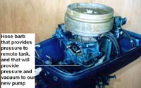 The key to making this pump work in this application is to convert the source of pressure for the pressure tank into a source of pressure and vacuum to operate the pump. Pressure for the pressure tank is supplied by a hose barb located on the intake manifold, usually directly under the carburetor. The crankcases of 2-cycle engines are sealed chambers which, unlike a 4-cycle engine, are under alternating cycles of pressure and vacuum as the piston travels up and down in the cylinder. As the piston travels upwards, the crankcase is under a vacuum and the fuel/air mixture is drawn into the crankcase from the carburetor. As the piston travels downward and develops pressure in the crankcase, the fuel/air mixture is forced out of the crankcase and through the transfer ports (fitted with transfer port covers) into the combustion chamber above the piston. On a multi-cylinder engine, each cylinder’s crankcase area is sealed from the other cylinders. On an “alternate firing” 2-cylinder engine, such as our subject OMC 5.5, one cylinder’s crankcase will be under pressure at the same time as the other is under vacuum.
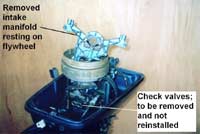
 The intake manifold is fitted with passages and also with “check valves” that permit pressure but not vacuum to be fed to the hose barb and then via hose to the pressure tank. In order for our new pump to work, we need to totally block the flow of pressure from one cylinder, and to remove the check valve from the passages from the other cylinder so that we get both pressure and vacuum from just that one cylinder. If one merely removed the check valves but did not close-off the passage from one of the two cylinders, the alternating pressure/vacuum pulsations from the two cylinders would cancel each other out. Once these modifications have been made to the intake manifold, the rest of the conversion merely involves mounting the pump somewhere on the engine, coupling a hose from the pump to the hose barb on the intake manifold, running a hose from the pump to the“quick connector” mounted on the engine, and finally running a hose from the pump to the carburetor.
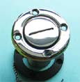
Changing the quick-connect fitting on the engine from the “pressure-tank-style” connector to the “fuel-pump-style” will allow you to use “off-the-shelf” OMC fuel hoses available just about anywhere. These fuel-pump-style connectors can be purchased through any Johnson and Evinrude dealer, or you can probably located a used fitting from a junked motor at an outboard swap meet. An alternative would be to use a fitting intended to adapt “generic” outboard fuel tanks to OMC fuel hoses. The fuel-pump-style OMC remote tank hose uses the same connector on both the motor-end and the tank-end. Most generic gasoline tanks come with a threaded suction connection and there are OMC-style connectors available to thread into them. There is no reason one of these tank fittings could not be adapted to be the engine fitting by threading-on a small pipe coupling and a hose barb . The fitting would obviously not bolt to the original mounting hole on the engine as the original equipment item would, but one could drill a mounting hole and mount the fitting in some fashion, or merely let it hang on it’s hose.
 One final comment on the quick connector; there are a couple of different versions of the original equipment fuel-pump-style OMC quick connect motor fitting; they all fit the same fuel hose and differ only in how they mount to the outboard motor. If you get the correct version, it will bolt right into the mounting hole vacated by the pressure tank quick connect fitting. If you end-up with the wrong style fitting, you can still make it work, but you will have to make your own mounting modifications.
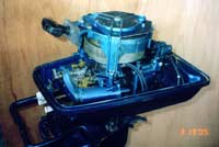
You will need to locate a spot “under the hood” of the engine where you can mount the fuel pump. Some of the later-style one-piece hoods have quite a bit of room available and mounting the pump will present no problems. Space is a little tight under the earlier “clam-shell” style hoods, however, and you will need to be careful that the pump does not interfere with anything else such as the spark plug wires, which move as the throttle is moved. Although it would not hurt to keep the hose runs as short as possible, the pump can be mounted just about anywhere under the hood and still work properly. The pump could even be mounted on the transom of the boat as long as it is within about 2 feet or so of the engine. There would need to be (3) hoses running between the pump and the engine, however, and all three hoses would need to be disconnected in order to remove the engine from the boat.
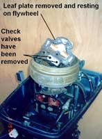
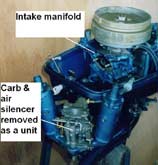
 Follow along on the parts diagram (left - click to enlarge) as we begin: Remove the carburetor (#56) by removing the two nuts which hold it to the intake manifold (#43); it will probably be necessary to remove the needle valves and packing nuts (#’s 39, 74, & 77) and maybe even the air silencer (#42) in order to remove the carburetor, depending upon the style of cowling that your engine has. I disconnected the carb throttle linkage at (#51) on the ‘59. Set the carb aside where it won’t be damaged, and remove the screws securing the intake manifold (#43) and remove the manifold and set aside. If you do not damage the gasket (#21) you can reuse it. You are now looking at the leaf plate (#30). Note the check valves for the pressure system (#’s 26, 27, 28, & 29); remove the leaf plate from the engine being careful not to damage the gasket behind and being especially careful not to damage the reed valves and hardware mounted on the backside of the leaf plate. Remove parts #26 through #29; you will not be using them but you should probably hang-on to them in case you ever want to convert your engine back to pressure tank use.
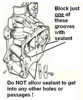
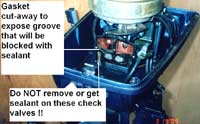
You are now looking at gasket (#22) assuming it stayed stuck to the engine; if the gasket came off with the leaf plate, so much the better. If it is stuck to the front of the crankcase, then do not damage it by attempting to remove it. Note the curving grooves in the face of the crankcase; these are the passages that conduct pressure and vacuum from each cylinder to the check valves; we want to block-off one (but NOT both) of these passages; I blocked the Starboard one but I really don’t think it matters which one is blocked. I used “hard-setting” gasket cement to fill the groove to seal it off. You can use something like epoxy if you wish, but if you should try to convert the engine back to the pressure tank in the future, the gasket cement might be easier to remove. Plus epoxy tends to soften when exposed to heat.