| Designing NACA
0000 Foil Sections
I do not claim to be any sort of expert
on the subject of foil design. I have only read up
on the subject and experimented with various tools
that I now own or have downloaded off the internet.
With that said, I only claim to be an interested observer
and tinkerer who likes to figure out how things work;
and spread any information that I have gained to other
tinkerers of like mind. Ducks of a feather so to speak.
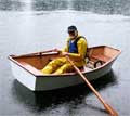
When I was close to finishing the construction of
my first 8ft Nuthatch
Pram, I started thinking about what type
of rudder and daggerboard I would need and how big
each would have to be. That started a series of long
searches on the internet for informational theory,
and articles on foil design and construction. I found
some good sites here and there, and gleaned as much
as I could about the concept of foil design. I even
read several books on sails, hulls, and foil design
by C.J. Marchaj. The books are intended for more than
the casual observer; and/or those looking for an aid
in getting to sleep. It wasn't until after I had copied
down a very complicated mathematical formula for foil
design, to put in a series of cells in a spreadsheet;
that I came across the NACA4gen
program online in a zip file.
A quick download and install brought up a very basic
program in DOS. Luckily, I'm old enough to have cut
my computer teeth (still have most of them) in the
dark days of DOS. Always wanted a Mac in those days,
but couldn't afford one. Do you remember the blank
screen and the blinking prompt? Or all the sticky
notes with obscure symbols and letters stuck to the
monitor to remember how to make DOS work on your $5000
IBM XT?
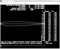
The 4Gen program just asks a couple of basic questions
with "mouse less" keyboard strokes. What's
the NACA number? Enter your XXXX number and then the
"cord" length (fore and aft width of foil,
not thickness). The program then spits out a diagram
of the foil and a text box to the right with the X
distances on the cord starting at the leading edge;
and the Y (+/–) offsets from the cord. There's
not much to the program, but the information is very
helpful. You will be generating several program inputs/outputs
until you find the "thickness" you need
for your foil. We will come back to this again later
in the story.
A little regression here, as older people always
seem to do. Stories always need a bit of filler to
make a point. Think of it like fiber in your diet.
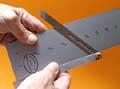
Before I ever started looking for foil information,
I had played around with several blanks of 5/4ths
cedar. I knew what a foil should look like from sailing
other boats, and also from spending large sums of
money for the "go fast" fins I used on my
sailboards. "Try this one out, everybody
at the Gorge is using it!" I have some very
nice fins in the loft of my barn that the spiders
hide under now. So I would lay out some lines on the
blanks and rasp away, saw away, plane away, and throw
away. I eventually got one that looked ok, but the
thickness was a little off from side to side. I did
some more rasping to even it out; but what looked
like a foil close to an NACA 0010 when I started,
became an 0006. I had other things to do so I set
it aside. When I came back to it again, the foil had
warped to port. I read an article online about cutting
the cedar blanks into 1x1's and gluing them back together
after you change each one's location in the pile and
swap ends on alternating sticks. The alternating method
should reduce any chance of warping that may occur
later. I have one untouched blank glued up, but I
got strip foiled, Hallelujah, before I needed to use
it.
I got inspired one day cleaning up some 1/8"
scrap from making one of the boat models
you see in
other stories, hanging on the
wall in the background of my shop. I stacked several
of the pieces on top of one another and the light
came on. Now I only needed to find a way to figure
out how to do it. The 4Gen program gave me the numbers,
but I needed to add the necessary layers of 1/8"
plywood to the foil's cross section. Looking at the
foil outline in the 4Gen program gave me an idea.
I wondered if the program I used to design the hulls
of my boats could also generate the bezier curves
of the foil? No scab goes un-scratched here.
I copied down the numbers off the monitor screen
(use the screen capture
program linked at the end of this story and print
it out) onto a scrap of paper, and used
them to set up the "guides" (adjustable
grid) on the drawing page of my program. The main
information for us that 4Gen spits out, is the "thickness"
of the foil and how far back from the leading edge
that point is. On the bottom of page two of the accompanying
PDF file
for a NACA 0010 – 12 inch foil; the maximum
Y(+/–) measurement is 0.600 inches, and the
X distance is 3.60 inches from the leading edge. That
gives us a foil that is 1.20 inches thick and a cord
of 12 inches. The thickness will give us problems
as that is only 9.6 strips of ply, but is close enough
for this story. As I alluded to earlier, you will
be generating several 4Gen lists as you figure out
the foil that you want to make. You will want to see
what the 4Gen program generated, and what was the
overall thickness for each iteration; and how close
that doubled Y number was to a full thickness stack.
An odd number is ok, as the very center can be a single
sheet with even numbers of layers on either side;
as in the PDF example.
Note: I found the screen capture
program Captura
1.0 on the internet and have been very
happy with it's functionality. It's a very simple
program to use with the 4Gen program; and any other
uses you may have. After you have input your NACA
number and cord length, the program generates the
foil shape. Use the Control-C command to exit the
program, or type QUIT. Open the Captura program;
use the select area command and crop out the DOS
window with the 4Gen information. Save the file,
and remember to add the (dot)jpg file extension.
I have added a screen capture folder in my Irfanview
photo directory so I always know where they will
be. You can then either print out the file, or run
it minimized in the drawing program window as you
do your figuring.
 |
|
Time for another side trip on computer programs.
The one I use everyday is no longer available, and
I can't find anything out there that comes close to
the ease of use and functionality that it has. I was
still using Win3.1 on a 386-25DX when I first got
it, and it still works on my P4 XP machine. Except
that Bill can't leave well enough alone, and now I
have trouble putting text in my drawings; and only
with M's and W's. Something to do with OpenType fonts,
the bastard child of TrueType. I was Beta testing
a 2.0 version of the program, but Win95 came out before
it was bug proofed; and they shelved it, even though
it worked fine on 95. Both Adobe Illustrator and PageMaker
would have been shelfware years ago if they had finished
ProDraw 2.0 on time.
You are in luck, in that the drawing program in OpenOffice.org
and the vector drawing program Inkscape
can do the tasks for laying out the foil cross sections.
Both are FREE, but neither touches ProDraw in power
or ease of use. Look for the links to both programs
at the end of this story.
Note: The rest of the story will assume
that you have one of the vector drawing programs
I have talked about or familiarity with the one
you already own.
With your drawing program running and on a blank
page, go to where you change the paper size and orientation.
You will be using 8 1/2 x 14 inch paper in the landscape
format. Also find and set the rulers to inches.
We will start by bringing in the first two "guides".
Usually dragged on to the drawing area from the top
and left hand borders. One will be a vertical, and
one will be a horizontal guide. Place the vertical
guide close to the left hand side of the page so you
have enough room to draw a 12 inch foil.
Find the "reset 0/0" button on the drawing
page and move it to the point where the guides cross.
The button is usually in the upper left corner of
the drawing boundary. Drag it to the intersection
of the guides. Look in the menus for the "snap
to guides" entry and select it. Look for the
"Zoom" function of the program and zoom
in on your new 0/0 point to see that it is actually
on the mark. Or find the "edit guides" dialog
box and make the adjustments there. Both should be
0/0.
In drawing #1 of the PDF
file that comes with the story, I have
added vertical guides at the maxim thickness point
(3.60) and at 6.0, 9.0, and 12.0 inches; and a horizontal
guide set at (0.600). Once you do this a few times
and prove to yourself that this method works; you
will only need the leading edge, maximum thickness,
and trailing edge vertical guides lined up on the
horizontal centerline guide.
Now comes the "fun" part. Don't you hate
it when people say that, cause you know it ain't true.
You need to find the "Bezier Curve" tool
to draw the "three point" line in drawing
#2, to form one half of the foil's outline. Good time
to look in "Help", as if it ever does. In
OpenDraw in OpenOffice.org,
it's in the tool bar on the left side of the drawing
page. Grouped with several other tools that slide
out to the right. Hold the mouse curser over the lower
left button in the group and it should say "curve"
or something like that. Click it and move the "cross"
back to the drawing and click the (0,0) spot on the
guides. Keep the left button down as you drag to where
the (0.600, 3.60) guides cross. Click there and go
on to the end point where the guides cross at (0,
12.0). Double click to end the line. You are done
with the curve drawing tool, and can go back to the
"pointer", aka the "selection tool".
Who's on first, what's up next?
OpenOffice.org can be a bear when dealing with the
handle points. Inkscape is easier, but as you have
found out, setting the 0/0 point doesn't exist. So
you have to add 1 to all the measurements on the X-axis.
0 is 1, 3.60 is 4.60, 12 is now 13. If you have another
program, or know how to use any of them; just make
sure the end points at 0/0 and 0/12 don't have any
"handles" sticking out that are attached
to the end "points". You want them
to be just "corner" points without any handles.
You will know something is wrong by the funky way
the line curves into the end points.
Double click the .600/3.60 handle point to select
it and then go looking for where the turn into "symmetrical"
point button is located. Make the .600/3.60 point
a symmetrical point and drag out the handle points.
You may have to put the mouse over the point, click
and drag out the handles. They may be looped in the
wrong direction, but you just need to twirl them around
to the correct orientation and drag them out. If the
end points are not corner points and have handles
attached; the curve you get will not look like the
one shown in drawing #3.
Drawing #3 on page 1 of the PDF
file, shows a horizontal guide centered
on the .600/3.60 point. Keep the point handle lined
up with the guide, and drag it out to the vertical
guide at 0/0 and release. That's it, you have just
created one half of the foil section. Now select your
new curve and go looking for the copy and flip commands.
Line up the leading edge point of the new flipped
curve (drag the line and not
the end point!) with the parent curve and go
looking for the "join" or "combine"
command. Make it so #1.
You can use a fill color to show that the joining
worked and can now save your file. You do save your
files right? You can move/set some guides to check
for yourself that the Y(+/-) values at the X distances;
do fall on (or too close to actually measure in the
real world) the arcs.
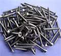
To figure out how many of the 1/8" layers you
will need; divide the total thickness (1.2) by the
thickness of one layer of ply (.1250). We get 9.6;
which works out to an odd number of ply's. So I "copy"
and "paste" a new cloned foil, and drag
it to an area below our first. Line up the leading
edge point on the vertical 0 guide. Drag
the foil and not the point. Drag down a new
horizontal guide to intersect with the leading edge
point. Drag down a a new 0/0 point at that new intersection
and to reset the 0/0 grid for a new task.
Add new horizontal guides above and below the 0/0
point. Go to the edit guides area and set these new
guides to +/- 0.0625. This will give you the thickness
of one sheet, split/centered over the new 0/0 horizontal
guide. Now take a pencil and paper and add 0.1250
to the 0.0625 numbers. This will give you the numerical
values (+/-) for the next pair of guides. Do this
four more times for a series of guide lines above
and below the 0/0 centerline of the foil.
Now fine the "rectangle" drawing tool
and drag one out starting at the location of the upper
corner of the "center" strip of plywood.
Drag this box out to the end and down at the - 0.0625/12
location. You have the first layer of plywood. If
it is still selected, click a color and fill it. You
will be using different "matched" colors
for each side of the foil. As I have done on page
2 of the PDF file.
You can see where one of the upper and lower horizontal
guides for the next layer of plywood crosses the foil
arc and where it also ends on the trailing edge. Place
vertical guides at those locations and drag out a
rectangle box using them as the end points for that
layer of plywood. Repeat the process with the remaining
layers. You now have the locations of the starting
and ending points of the "strip widths".
Click on the vertical guides to check the values given
in the editing dialog box. Adjust to a normal measurement
as needed, but still staying in the cross section
boundaries. On this cross section, the starting and
ending points fall close enough to standard measurements;
and we will use them as is, for constructing our NACA
0010 – 12 foil.
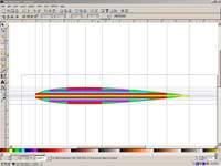
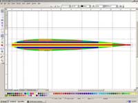
The following screen capture jpg's show completed
foil drawings done with the Inkscape (left) and Open
Office (right) programs.
 |
|
The only thing left to discuss is what shaping needs
to be done at the tips of the foils. As I stated at
the beginning of this story; I'm not an expert on
any of the fine points of foil design. I can only
go by the information in the articles that I have
read, the shapes of the foils I have used with other
small boats; and in my collection of sailboard fins
and daggerboards. All of them have some shaping done
to the tips. Part of it is reducing wetted surfaces;
and part is increased performance. Water will prefer
to go around a "shaped" tip than across
a square one. This induces less turbulence off the
foil's tip and trailing edge. Less turbulence off
the daggerboard will help the rudder maintain it's
grip in the water when it gets there. I like to have
straight leading edges and taper off the trailing
edges of my daggerboard foils. This also gives me
a longer section of the thickest part of the foil's
cross section, for strength at the ends. This helps
when you are standing on the daggerboard during a
self rescue. The rudders, I leave a little boxy to
maintain working surface area.
I still haven't worked up any standard (researched)
numerical information about how big a foil should
be in relation to the size of the hull. I've been
leaning towards {db-cord in inches, is equal to hull
length in feet as inches, plus two inches}; so a 10ft
boat would have a 12 inch daggerboard cord (10"+2"=12").
The exposed length of the daggerboard is twice the
length of the cord. So a NACA 0010-12 would have 24"
exposed below the keel of the boat. The overall length
would be determined by the daggerboard trunk height,
plus room for the hand grip and depth stop. I try
to size the rudder to be 1/3 of the exposed surface
area of a fully lowered daggerboard. So far my sailing
boats have had no bad habits, and the estimated CLR's
(with fully extended daggerboard, no rudder) from
my scaled half model hulls, have been right on the
money to their full sized sisters. Push at that point
on the hull while it is sitting next to the dock,
and the boat moves away with no induced turning.
That's it, with the programs we have just used, you
can now design your own NACA 0000 foils. I hope all
this made some sense and I haven't confused you about
the process. If you don't want to download, purchase,
or learn a new computer program; everything can be
done with pencil and paper after you have generated
the numbers with the 4Gen program. You can layout
the X and Y values on graph pager, and outline the
foil's arc with a french curve and be close enough
to make a template. You can then figure out how many
plywood sheets are required and how wide each needs
to be from this method too.
The following are some links to sites for free programs
that I have used to help with this story. For ease
of use; the Inkscape vector program is less hair pulling,
but still in early development. I will be updating
the Inkscape program on my computer as it gains in
features and usability. It looks like a winner. OpenOffice.org
2.02 is a truly great, full featured "Office
Suite" program now, and can stomp "clippy"
into his much needed oblivion.
Links
Thanks again for reading my stories. I hope you enjoy
reading them as much as I do writing them. My next
story will be on how and why I design boats the way
I do. Until then, stitch and glue and stylish too.
Warren
Messer
Red Barn Boats

Other Articles by Warren Messer
|