| To Part Two
A while back we looked at rehabilitating partly-dead power tools.
Now we are going to examine a subcategory – cordless tools.
Like last time, in this rehabilitation I am strictly an enabler.
And well I should be! We all love cordless tools—we can
bring the tool to the boat without a wheelbarrow full of insulated
copper.
But the batteries do not last forever, which leaves us particularly
vulnerable to the whims of the manufacturer. Don’t get me
wrong, I’m in favor of tool companies coming up with new
and better ways of doing things. But it can be terribly aggravating
when one has a perfectly good tool that gets “orphaned”
when the company moves on.
Well, let’s back up to the beginning.
About six years ago I got a Black & Decker 14.4v cordless
drill. It came with a little wall wart charger. This was the first
problem. There was no current-limiting circuit on the wall wart,
and drained NiCd batteries can pull a lot of current. It rather
quickly burned out, which was no real surprise. So I went to charging
battery packs with an automotive battery charger.
This works...for a while. On the 6 amp, 12 volt setting it puts
out enough voltage to charge a 14.4v battery, but not very fast.
One problem with this is that the slow charge tends to stratify
the electrolyte, which reduces capacity. The other problem is
that you need to keep an eye on it. Leave it too long and you
overheat and ruin the batteries! Which, of course, I did. I was
able to reform the cells once (see https://www.batteryuniversity.com/
for details), but the second time I left it charging too long
there was no bringing it back. I thought about replacing the cells,
but buying a new pack cost about the same. Easy choice.
When I made the same mistake on my second battery pack I decided
it might be time to spend the $25 to get Black & Decker’s
smart charger, which should prevent such nonsense. (So I’m
a slow learner…) Besides, I dropped the auto battery charger
and something shorted in the transformer – now it only puts
out 13 volts on its highest setting—not enough to even touch
a 14.4 volt NiCd.
So far these had all been things I’m used to dealing with.
You know, normal entropy.
But then I had a hard time finding the appropriate charger. They
seemed to have disappeared from the face of the earth. When I
checked out Black & Decker’s website I figured out why
– they had moved on to a new battery design. I did find
my style of charger for $35, but the battery packs had gone up
to $60! This did not bode well at all. I considered watching for
dead packs on Ebay and rebuilding them with new cells, but the
new style of battery cost about the same as the cells to rebuild
an old one. If I were buying anything, it might make more sense
to go with the new style. Or maybe a better brand.
Unless only some of the cells are dead.
Battery Diagnosis
There are plenty of articles online about how to replace all
of the cells in a battery, but how do you know which ones need
replacing? There’s no sense in wasting money and cadmium.
The must-read article on this topic can be found at https://homepage.ntlworld.com/wilf.james/nicads.htm.
The author, James Wilf, tells us not only how to diagnose the
cells, but also how to build a cheap charger. One caveat is that
the author is British, so there are some minor terminology gaps.
For example, a “trafficator” is a type automotive
directional signal we never used here in North America. (…which
I never would have known without Google.) Anyway, Mr. Wilf covers
the “why” in some depth, so you should read it. I
will only look at the “how”.
What we need to do is find the internal resistance of each individual
cell, as this is a pretty good estimate of how good a cell is.
To test the cells, we must first take the battery apart. You need
to be able to get test leads on both sides of each cell. Here’s
the battery pulled apart.
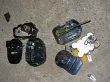 |
Battery guts |
This is usually just a matter of a few screws, but sometimes
the clips come off. Don’t lose them! You’ll need to
cut off a shrink plastic cover (usually black) and peel off a
sticky plastic insulator top and bottom.
 |
Cell cover |
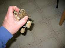
Now we need a good voltmeter and either a flashlight bulb or
a low-value resistor. I used an 8 ohm 25 watt resistor, since
I had one for testing amplifiers. Yours doesn’t need to
be anywhere near 25 watts. A half-watt resistor would be fine
at 8 ohms.
Don't have 8 ohms? Any resistance small enough to significantly
load the battery will work. For these cells 11 ohms would discharge
them at 120mA, which is what these cells are rated for. I'm drawing
a bit more current than I should by using only 8 ohms.
I guess you'll want to know how I figured that out.
Ohm's Law
Anyone who experiments with things electrical gets to be pretty
good friends with Georg Ohm, who in 1827 figured out that voltage
drop across a resistance is proportional to current. It's like
a mantra:
V=IR
V is voltage in volts
I is current in amperes
R is resistance in ohms
Since we knew the cell voltage of 1.3v and the current of 0.120
amps, it is simple to calculate the resulting resistance.
...back to internal resistances...
We measure the voltage of each cell with just the tester, then
measure it again with the resistance draining the cell. If you
think about it, this makes sense. We don't care so much about
the cell voltage when it's just sitting there – we want
to know what it can do when we're using it.
It is easiest to use jumpers and connect the resistor to the
test leads. Here I’ve used a spreadsheet to do this for
two drill batteries – a Ryobi and the Black & Decker.
| Drill |
Cell # |
Voc |
V8ohm |
amps |
Vdiff |
Rcell |
| Ryo |
1 |
0 |
|
0.00 |
0.00 |
n/a |
| Ryo |
2 |
0 |
|
0.00 |
0.00 |
n/a |
| Ryo |
3 |
1.209 |
0.603 |
0.08 |
0.61 |
8.04 |
| Ryo |
4 |
0 |
|
0.00 |
0.00 |
n/a |
| Ryo |
5 |
1.271 |
1.24 |
0.16 |
0.03 |
0.20 |
| Ryo |
6 |
0 |
|
0.00 |
0.00 |
n/a |
| Ryo |
7 |
1.279 |
1.243 |
0.16 |
0.04 |
0.23 |
| Ryo |
8 |
0 |
|
0.00 |
0.00 |
n/a |
| Ryo |
9 |
1.225 |
1.171 |
0.15 |
0.05 |
0.37 |
| Ryo |
10 |
1.268 |
1.107 |
0.14 |
0.16 |
1.16 |
| Ryo |
11 |
0 |
|
0.00 |
0.00 |
n/a |
| Ryo |
12 |
1.229 |
1.063 |
0.13 |
0.17 |
1.25 |
| |
|
|
|
|
|
|
| B&D |
1 |
1.299 |
1.268 |
0.16 |
0.03 |
0.20 |
| B&D |
2 |
1.306 |
1.291 |
0.16 |
0.02 |
0.09 |
| B&D |
3 |
1.323 |
1.308 |
0.16 |
0.01 |
0.09 |
| B&D |
4 |
1.295 |
1.275 |
0.16 |
0.02 |
0.13 |
| B&D |
5 |
1.29 |
1.276 |
0.16 |
0.01 |
0.09 |
| B&D |
6 |
1.198 |
1.121 |
0.14 |
0.08 |
0.55 |
| B&D |
7 |
1.299 |
1.27 |
0.16 |
0.03 |
0.18 |
| B&D |
8 |
1.146 |
0.994 |
0.12 |
0.15 |
1.22 |
| B&D |
9 |
1.165 |
0.6 |
0.08 |
0.57 |
7.53 |
| B&D |
10 |
1.32 |
1.303 |
0.16 |
0.02 |
0.10 |
| B&D |
11 |
1.319 |
1.304 |
0.16 |
0.01 |
0.09 |
| B&D |
12 |
1.289 |
1.273 |
0.16 |
0.02 |
0.10 |
Voc = open circuit voltage – just
the tester on the cell.
V8ohm = voltage with the 8 ohm resistor drawing
current from the cell
Amps = V8ohm divided by the resistance (8 ohms)
equals current in amps
Vdiff = Voc minus V8ohm – this difference
in voltage is due to the cell’s internal resistance
Rcell = cell resistance is Vdiff divided by amps
Based on open circuit voltage alone we can see that the Ryobi
has 6 fully dead cells. The other cell voltages don’t look
so great either, since we should be seeing around 1.3. This battery
has probably been abused pretty badly. If this battery pack were
for something better than a Ryobi, I’d probably replace
all cells. I doubt this one will get such royal treatment. The
Black and Decker looks better, but cells 6, 8 and 9 look a bit
weak. Let’s figure out how weak.
Now we put them under load and get the “V8ohm” column.
Three more of the Ryobi’s cells drop off disturbingly. So
we do the math to get internal resistances – the higher
the resistance, the worse the cell. In the Ryobi, only cells 5,
7 and 9 are under half an ohm. (Half and ohm isn’t very
good either!) The numbers also tell the tale on the B&D –
cell 9 is the stand-out worst, and 6 and 8 are pretty bad too
– much as we suspected from the open circuit readings. But
now we can also see that cell 1 might not be long for this world.
So now we know which cells to replace. By the way, those cell
numbers were something I arbitrarily assigned to keep track of
which cells were bad. You won’t see it printed anywhere
in the battery, but writing numbers on the cells with permanent
marker does make life easier.
Replacing Cells
If you do a web search on the numbers on your cells, you will
quickly find vendors for replacements. Be sure to get cells with
tabs on them – soldering to the cell can easily overheat
and destroy it. The tab provides some margin of safety. Better
yet, go find a local store than sells specialty batteries. In
my area it's a place called Batteries + Bulbs. They can spot weld
the cells in, and it's included in the cost of the cell! And of
course no shipping change. Easy choice. Normally this can even
be done while you wait, but I stopped in a Sunday afternoon and
the technician had just left for the day. I left the battery for
them to attend to, since I wasn’t exactly using it anyway.
For now let's cobble together the best (least bad) cells from
the two Ryobi batteries to make a half-decent one. The internal
resistances on the second pack were not very encouraging, but
I think we can get most of the cells under half an ohm. This might
hold me over until I get the B&D fixed up.
I cut the tabs using an angle grinder very carefully. A Dremel
would be a lot better, but my dad had it at the time. A big wire
cutter might work too, but would probably chew up the tab a lot
more. In any case, Leave the bulk of the tab on the side of the
good cell.
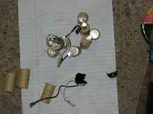 |
Cells apart |
Next step is to figure out how they will fit together. This
is tricky because the angle of the tabs can be wrong for their
new location. I got around this by flipping the tabs into a “U”
shape and soldering wire to the bottom.
 |
Battery soldering |
This increases the thickness of the pack, and I had to get rid
of the stiff plastic insulator to make it fit into the case. I
used regular electrical tape for insulation. This probably isn’t
as durable as the real thing, but I don’t expect these cells
to last much longer anyway.
This is not the easiest soldering job in the world – you
need to solder it quickly, and with enough-but-only-just-enough
heat. Blow on it just as soon as the joint is heated. Make sure
you pre-tin both parts of the joint before putting it together,
and above all clean off all sticky junk from the insulator before
starting. If you have heat sink clips, use them (even though I
forgot to). All of these will help you get a good joint with less
heat to the cell.
 |
Battery soldered |
The charger says it’s good!
 |
Battery charged |
And indeed, it now has the power to drive screws in a meaningful
way. But the battery was noticeably warm after charging. This
charger is supposed to be smart enough to prevent that, but it
appears not to. So we might need a better charging method here.
Speaking of chargers, we still need to deal with putting one
together for the Black & Decker battery that’s in the
shop. We’ll get to that next time.
Rob Rohde-Szudy
Mazomanie, Wisconsin, USA
robrohdeszudy@yahoo.com
*****
|