| To Part One
Helensboat, A Jim Michalak Trilars Continued
|
When the fillets have set, the boat is flipped back upside down, the duct tape removed and the chines belt sanded to a fair curve. |
|
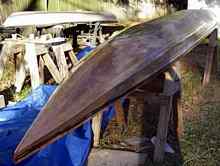
At this point, my friend Olivier Chamel came over and we filleted and taped the outside chines. We had hoped to put a layer of glass on the entire outside, but rain was threatening and we had to get the boat covered up. Yes, this was an outside build and I took a lot of care to keep the boat well covered until the outside of the hull was completely glassed. |
|
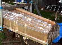
The actual glassing of the hull had its own mini-disaster. I use one of those yellow auto body putty squeegees to spread the epoxy on the bottom and bilge panels and a brush on the vertical topside panels. I had most of the glass on and a so far wrinkle-free job when the pressure of using the squeegee pushed the stern of the boat off the sawhorse and it rolled over and fell on the ground. I would have cried, but quick action was needed. I got the boat back on the sawhorses and most of the glass back in place. There were a few puckers and some dirt and grass but overall I was lucky. |
|
The puckers from the mishap were cut out and taped over, making for a little more fairing work later. |
|
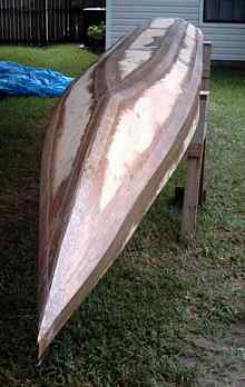
Extra glass was applied at the forward part of the bottom, where extra abuse is likely during beaching. An epoxy soaked rope was applied down the leading edge of the bow for extra abrasion resistance, and then glassed over. |
|
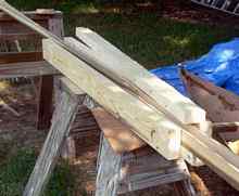
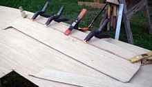
The gunwale reinforcements were next. I had some nice tulip poplar left over from earlier projects, but it wasn’t 20 feet long. This simple jig let me cut scarfs in the wood so a sufficient length could be glued up. |
|
The bulkheads were removed and the ’wales applied. Here the second (starboard) strake is glued and screwed in place. The wales add a lot of strength and take the last waviness out of the hull. The tricky part of the gunwales is they are beveled at the bow and along the cockpit, to match the angle of the deck. But they are not beveled behind the cockpit, where the stern deck is flat. I cut the bevel so it stopped just forward of the aft bulkhead, and then did the last bit with a file. |
|
|
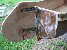
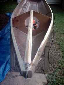
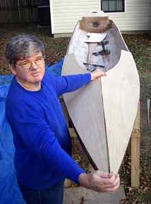
Before going further, I also made the rudder and swinging blade, as I wanted to work out the rudder mount, drill the holes, and install the backing plates before the inside of the hull was finished and the deck installed. Here the rudder is test fitted. The inset for the pintles allows for easy mounting of the swinging blade without interference from the bolts or metal straps. The blade itself was lengthened three inches to accommodate for Helensboat’s extra length over a Larsboat. Oversized holes were drilled and filled with graphite powder and thickened epoxy. These will act as bearings for the pivot bolt and also prevent rot from starting at the bolt and control line holes. There’s a cutout in the middle two layers near the bottom of the blade, filled with lead so the blade naturally drops. |
|
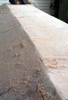
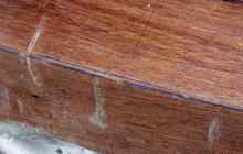
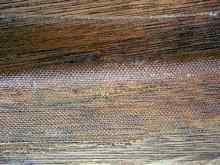
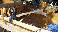
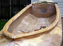
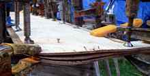
Now it was time to glass the inside of the hull. The inside filleting was completed and where necessary the previous filleting was sanded smooth. The inside chines were taped. Here’s a closeup of the tape. |
|
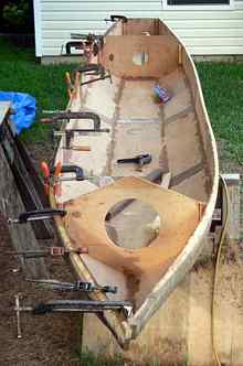
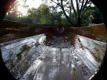
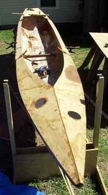
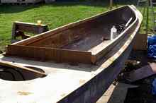
Then the inside of the boat completely glassed. It’s always amazing how that layer of glass on the inside adds so much rigidity to the boat. Here’s a shot of the cockpit taken through the access hole to the stern watertight compartment. Watertight deckplates will be installed in this and other access holes you see in these pictures. |
|
The skeg was also added at this time. |
|
The center beam for the bow was installed and beveled for the deck. The beam for the stern compartment isn’t in the plans, but I decided to add it because the ply was thinner than specified. It’s held by fillets of thickened epoxy. |
|
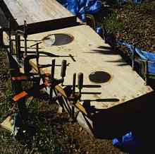
The stern deck was fitted, glued, and fastened in place. I opted for two deckplates. Along with deckplate on the aft bulkhead, there should be plenty of access to this compartment. |
|
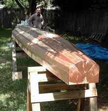
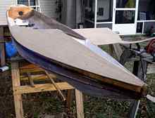
The part of Helensboat the produced the most trepidation for me was the deck. I thought it would need to be redrawn on plans to accommodate the longer length of the cockpit, but studying the plans showed that the inside edge of the deck follows the sheer for most of its length. The curve at the forward part of the cockpit can be taken from the Larsboat plans. A sheet of plywood was clamped and braced in place over half of the forward bow. That allowed the sheer, centerline, and location of the forward bulkhead to be marked. From that, the curve of the inside edge was drawn from dimensions provided on the plans. The deck was cut a little oversize and then put in place for final fitting. The process was duplicated on the other side. A couple hours and my worst nightmare job for the project was done with nary a hitch. |
|
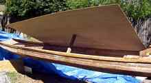 |
A sheet of ply is clamped and propped in place so the aft part of the deck can be marked. The total length of the deck from the bow to the end of the cockpit was a hair over 16 feet, so two butt straps were needed on each side. |
|
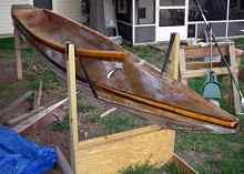
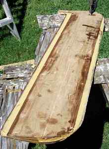
The deck is finished, except for final trimming. |
|
I split a 1x4 for the coaming. Because of the extreme curve of at the forward end of the cockpit, I split each side again. Above, the bottom of the port side is attached. |
|
Here the top and bottom of the coaming is installed on both sides. |
|
In case we want a spray skirt, I laminated a lip around the coaming. The sweeping curve of the coaming adds a graceful note to the design. |
|
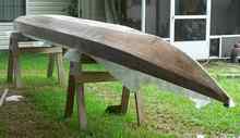
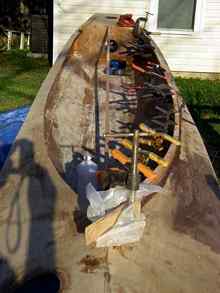
The deck is sealed. Now come weeks of fairing . . . |
|
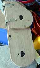
While the decking and finishing was going on, I made the leeboard of Helensboat. Because of its larger size, I increased the thickness from three quarters to a full inch, and added six inches to the length of the board specified for Trilars. Taking advantage of the 4 mm ply, I tried a different way to get a wing shape for the board. First I cut one layer for the leeboard, full sized. About a third of the way from the front edge, I glued a narrow strip of quarter-inch ply on each side. This becomes the middle of what will be a hollow board. |
|
Next, two outer layers are cut. These are not full width, but rather are set back from the leading and trailing edges; about a half inch from the leading edge and a inch from the trailing edge. These pieces are lined up on either side of the center piece and the leading and trailing edges clamped and glued into place with thickened epoxy. The side pieces are bent over the quarter inch strips, which gives the board a fair, wing shape. |
|
The gaps at the leading and trailing edges are filled with thickened epoxy. The three 4 mm layers plus the two quarter inch (6 mm) strips gives a finished thickness of one inch and the curved outer layers give exceptional stiffness to the board. An eight-inch piece of epoxy soaked Dacron rope is attached to the leading edge for abrasion resistance and after final fairing the board is glassed. It’s not necessary but I filled the hollow board with epoxy, which will probably give it negative buoyancy. If it weren’t filled with epoxy, the pivot bolt hole would have to be sealed with thickened epoxy to prevent the board from filling with water during use. |
The next steps are to install the leeboard and the mast partners and steps. The footpedals and steering lines for the rudder are also on the list. Then the final sanding and painting of the main hull and testing it out for padding (no, it’s not necessary to have the leeboard installed for the paddling test, but I want to get it done).
Then it will be on to building the amas and rigging for sailing.
(C) 2011, Gary and Helen Blankenship
 |