|
[This article is best read top to bottom including the photo captions. ed.]
The American whaleboat was crewed by 6 men, one of whom was the helmsman: that left 5 to row. Since the boat is very shapely with a continuous changing beam from stem to stern, the length of the single banked oars varies with the rowing station. Further, the rower sits all the way opposite the oar lock (not in the center of the thwart), thus giving a longer and more powerful lever arm. To balance the three oars to starboard against two to port, the two short oars and the long oar (with a slightly smaller blade) rowed against two oars of intermediate size: in this boat the oars were, from fore to aft: 15' starboard, 16' port, 17' stb' 16' port, 15 ' stb. One might puzzle about this and think the balance was off, but as my friend Moray says " These men were not fools", and these details were worked out over a century of use. Perhaps someone with math skills could calculate the combined angular force to see if it balanced out in theory as well as practice.
The plans of the Newport News boat give the lengths of the oars and a drawing of the shape, with two cross sectional measurements for each oar. The plans also provide the weights. You may recall that before I even started the boat, I made a 15' oar to assess my commitment to the project. I started with a square loom dimension of 3 1/2" and a terminal blade thickness of 5/8. This was much too heavy, and over the course of the boat building, I would take it out and whittle it down bit by bit, eventually ending up with an oar that was 2 1/2" at the square loom, 1 1/2" where the loom meets the blade and 3/8" at the tip. This weighed 18 # compared with the museum boat weight of 17.5#. This first oar became the model for all subsequent oars.
The oars are made in 8/4 ash (12' long and ripped to 3" wide) and laminated out of 6 pieces: two long sections are glued up with scarfs and then joined together. The shaft is tapered and then the blades are added. It is possible this could be done with wood glue since the oars do not live in the water, but I was too chicken and used epoxy.
Unless you have perfect lumber or a lot to waste there are some tricks to getting these long shafts straight. First of all when making the scarf joints, be sure the long pieces are as straight as possible, or lacking that, have reverse curves, so that when the pieces are joined the forces cancel out and the overall shaft is straight.
|
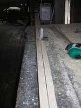
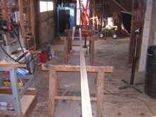
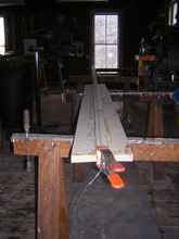
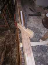
Photo 1 (P1) |
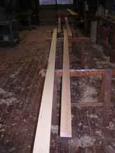
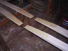
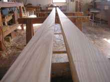
Photo 1 (P1) shows the long sections laid out. Sometimes rearranging what fits to what gives a straighter piece and better elimination of defects. I cut 1:8 scarfs on the bandsaw and finish with a hand plane. It is useful to stack the two pieces together for planing since any cant to the side will cancel out when the pieces are flipped and matched. |
|
P2 |
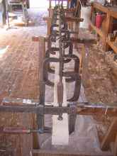
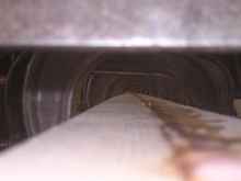
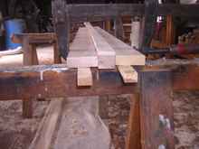
Photo 2 (P2) shows the stacked scarfs; I rough them up with a rasp to make a better glue surface. the surfaces are wet with unthickened epoxy (P3) and then spread with thickened glue and clamped. |
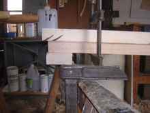
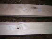
Remember that epoxy clamping is not super tight like wood glue; just tighten enough to close it up and hold it still. Now is the time to be sure they are aligned well; sight down the length of the stick and tap the ends with a hammer to straighten them out if needed (P4).
|
P4 |
When these are dry I run them through the planer to make a flat surface for the shaft glue up. Try them out in various configurations to see what gives the best straight length.
|
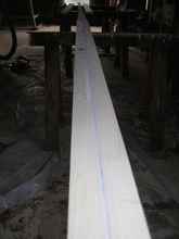
P5 |
P5 shows a shaft (pieces on edge) that hooks slightly to the left. If you spring it slightly before clamping it may straighten out. |
|
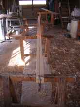
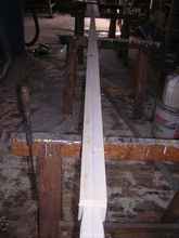
P6 |
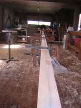
P6 shows the end of the hook, curve downward, set up on a block; the shaft sags downward slightly between the horses, and if it is clamped like this, it is straighter (P7). |
Make that glue line as straight as possible. I glued these up using 1/4" extra on each surface, thus the square dimension was 3" overall. There are also corrections that can be made if the flat plane curves.
|
P8 |
P8 shows two pieces that curve in opposite directions. If they are glued up stacking one on the other as they are laid out in the photo and the edges are clamped first, the piece is improved (P9). |
P10 shows the view down the length of this piece. This ash is pretty good but I did have some knots I couldn't avoid. When possible I placed these inside the thick square inboard section of the oar where I would not worry about them failing P11.
|
P10 |
|
P12 |
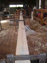
After the shaft is dry, it is time to decide how to lay it out. Use a snap line or better a thin cable ( like used to hang pictures) to lay out a straight center line and see where the best fit is (P12). |
If there is a curve
(there will be along a shaft 15+ feet long) use the straighter bit for the handle and strike a drawn centerline to the other end. Shaft measurements are then laid out at intervals and connected by straight lines.
|
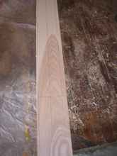
P13 |
P13 shows the centerline running slightly off center off at the blade end of the oar, but there is enough wood left to have a 1.5 " cross section. |
|
P14 |
P14 shows the offset measurements. If you are really ambitious you can decide which plane the blades lie in based on the grain pattern of the shaft; Pete Culler says that growth lines aligned with the plane of the blade will result in a more flexible shaft: grain perpendicular is stiffer. |
|
P15 |
P15. I chose more flexible. |
From a design point of view these are big oars and I reasoned that the flexibility would give a more gentle beginning to the power stroke; the blade yields initially and, once the rower has momentum, stiffens up. At the end of the power stroke there will be an elastic "kick" when the rower's reach is as far as it can go. (It is a little frightening how much of this project is based on hypothesis).
Now the shaft is tapered to final overall dimensions. I use the band saw to rough it out and the power plane to fair it, first on on the horizontal, then the vertical planes. The stationary planer brings the square inner shaft to final smooth dimensions quickly. With the shaft tapered, next comes the blades. These are planed to 3/4 " thickness and roughly 3" wide, 6' long. Again there are opportunities to correct twist and curve.
|
P16 |
P16 shows the tapered shaft and blades that have some hook to them. |
|
P17 |
By gluing them to the centerline in opposite curves, the bends cancel out (P17); the wedges aid in raising the thinner stock to the center of the shaft before clamping. If the shaft is crooked despite your best efforts (P18), the blades may straighten it out enough to be usable (P19). |
|
After the blades have dried, mark the centerline on the centerline of the oar (P20). |
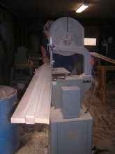
Use your pattern (based on that first oar and the plan drawing) to lay down the shape against the centerline, and cut it out on the band saw. Cutting these long curves on the bandsaw is made easier by rotating the saw as you cut, rather than trying to move the shaft of the oar side to side.
My saw has a rolling wheel for the movable base that is positioned right under the bandsaw column. In photo 23 I am pulling the column with my left hand while the shaft moves straight ahead on a roller stand. Photo 21 is the final rough shape.
|
P24 |
Now mark the centerline along the edge of the oar on both sides (P24). This photo shows one that came out right in the center of the end but since the edges are going to be thinned to 1/4" and the end of the oars is 3/8", there is some wiggle room. |
|
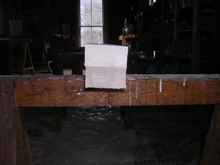
P25 |
A standard spar gauge lines off the 4 sided shaft for octagonal shaping (P25). |
This one has two nails that ride along the sides of the square and the pens are spaced by a ratio of 7/10/7; If it were in eigths, the distance from the nail would be 7/8, from pen center to pen center 10/8, and then 7/8 to the last nail. When drawing the lines along a tapering shaft be sure to keep the nails in contact with the sides of the square shaft.
Part Eight B Continues Tomorrow... |