| 1/5/97 thru 1/25/97 . . .
Rubens Nymph almost finished {now finished}. The decision now is if Phil
Bolger's BEE should be the next build. I already have the plans. The finished
boat should fit inside the truck. The recommended motor is 60 pounds / 8 HP.
There is also the potential to stretch the hull to 10 feet. {If 1 foot long trim tabs are
then added, the basic hull will look like the 11 foot mini-tug from Berkeley Engineering.
The seams are the only thing that is called out specifically for glassing.
However, a light weight glass sheathing would make sense if built as a production boat.
Hardboard template ; again a good idea if production is anticipated.
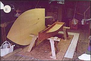
The low sawhorses should suit well. A foot shorter and 6 inches narrower than
RUBENS NYMPH, with the step should make a good fit. NOTE: cutting the 74 degree bevel was
good practice for cutting the stems.
 [NOTE:
the error blocks of OAK I have should make wonderful stems !! ] [NOTE:
the error blocks of OAK I have should make wonderful stems !! ]
2/12/97 . . .
Although Devlin's comments about RED CEDAR say it is LOW in strength and
BRITTLE, pieces sliced from 2x4 stock seem light, stiff, and strong. Used as an
epoxy/glass substrate, and for interior framing, in small boats should pose no problems.
3/27/97 . . .
Saw a copy of Bernie Wolford's catalog at the PILOTHOUSE {nautical book shop in
Philadelphia}. Read the comments about BEE and MICRO-TRAWLER.
BEE was the prototype of the STEP SHARPIE hull type. Proved successful enough
for Bolger to design an entire series of boats using this hull form. There was a picture
of BEE, at speed that looked very interesting.
[NOTE: Was Berkeley Engineering's series of mini-tugs from simultaneous
thoughts ?]
Other than Bernie's comments about a surge when suddenly stopped, and the
drawings comments about swamping {ANY small boat requires common sense use}, BEE looks
good.
With the notes about required stiffness, and the minor cost differences, 6 oz
tight weave might be a good idea for the box keel and hull bottom. 2.75 or 4oz for the
side panels.
Although the specifications call for filleting the hull bottom onto the box
keel, from the bottom, this sounds awkward and making for waste. A better approach seems
to be build the box keel, complete with interior glassing. Tack on the hull bottom, from
the bottom with epoxy fillet spot welds . When set, flip assembly over and complete the
filleting and glassing of the hull bottom.
The ball tool should work well here. I ve made two heads ; a 1 inch and a 1-1/4
inch. Wood balls and a couple coats of epoxy. Also, got a 1 inch Ceramic ball drawer pull.
The bottom flats or sponsons are narrow; a 15 inch section of cloth will do
nicely. The tight weave comes in 60 inch widths. At the price it seems prudent and
practical to cover the hull and keel bottoms.
[NOTE: Question for Payson or Bolger; will the added stiffening allow a lower
keelson ?]
Also, a 3/4in x 3/4in skid on each side of the bottom; backers to the keelsons,
should give reinforcement and allow shallower keelsons
With a size 9 inches shorter and 7 inches narrower than Rubens Nymph, she
should be easy to handle. Interesting to look at, especially in some WILD COLOR !!
4/8/97 . . .
Received the 2.75oz , 3.75 oz. , and 6 oz. Tight weave samples from RAKA. Made
test patches.
Oddly enough the 6oz tight weave is LESS expensive than the 4oz material, and
$3/yd MORE than the 2.75oz. !! [Larry Steeves was wrong - the 4oz is NOT more
expensive; it's 60inches wide V.S. 30inches of 3.75oz cloth - - - as of today anyway !]
4/10/97 . . .
The set samples look very interesting. The 3.75oz material is the ROUGHEST .
The tight weave is the SMOOTHEST . The 2.75oz is somewhere in between.
From a hand point of view the tight weave is STIFF as Larry said . The
coarseness of the 3.75oz material is probably due to the heavier YARN with a MORE OPEN
WEAVE.
Structurally the tight weave should be excellent for the HULL bottom, giving
extra stiffness. The other areas should use the 2.75oz with no problem. Should be easy to
fill. From the samples, the tight weave should need only slightly thickened resin to do
the job. { question for Payson or Bolger; the 6 oz tight weave is very stiff and when
wet-out gives a smooth, high glass-to-resin ratio surface covering. Would its use allow
substituting 1/4 inch ply for the 3/8 inch (bottom) called for on the 10-1/2 Foot Pointy
Skiff ? }
4/17/97 . . .
Have been giving more thought to structural considerations. The plans call the
3/4 in x 1-1/2 in frames, fastening frames . The transoms are ½ in ply. The epoxy fillets
should be strong enough to hold everything tight; especially if the exterior is sheathed
and the seams taped.
The written instructions say to, glue and nail the sides to the stem before
bending to the transom. Then secure to transom; box keel done first. If I epoxy and
screw, then secure with more epoxy and screws (2 inch NO-CO-RODE Drywall style ), AND use
3/4 inch ply instead of ½ inch, then could do without fastening frame.
Minimal cost saving, but significant time saved.
5/30/97 . . .
The more I think about it, the more I feel that BEE should be the next build
and why don t I just get on with it !!
6/15/97 . . .
Once I made up my mind, I had to get Joanne to go along, BEFORE the Nymph was
sold. At this point it's sort of O.K. {helping her out all day yesterday at the office may
have helped a bit}
At this point went over the drawings & comments again. The box keel transom
is ½ inch ply plus a slab of 3/4 inch material --- making a 1-1/4 inch transom !! And the
motor boards don t even bear on it!! The angled motor boards do pull on the center piece
of the upper transom fastening frame so I retract my original thought of using only a 3/4
inch transom and no frame. In fact I ve had some thoughts on how to add more flotation.
6/18/97 . . .
Got the basic wood at Home Depot yesterday; hardboard for templates, Waferboard
for base, ½ inch ply for Box Keel Bottom and Transom, and four pieces of Red Cedar - 5/4
x 6 x 8ft. About $56. in all. A 1/4 inch thicker frame won t hurt at all !!
Still having a mental debate if I should make a template of the box keel bottom
or just lay it out on the 1/2inch ply and cut. It's simply a 7ft 3in x 15-1/2in rectangle;
tapered at one end. The bottom is also very simple; almost a fattened version of the box
keel bottom. Again, is a template necessary for this part? It seems that the only
highly shaped parts are the panel sides and the transom. The rest relatively simple,
smooth curves. And they fit into the formed side panels.
Painted the template board. While waiting for it to dry, reviewed the building
notes again as to materials. It seems the part that takes the greatest beating is the HULL
BOTTOM. Also, if this part flexes the box keel sides can split. Therefore, this area seems
a good choice for the 6oz tight weave cloth.
I also think I ll modify something I read about using lay out battens. I will
paint it FLAT BLACK; on 3 sides. The side against the panel I ll leave clear; that way I
ll be able to see the grain orientation. Also, I ll make the major lines with a SHARP
BLACK FELT TIP; should be easier to see when cutting templates; stick to erasable pencil
with the wood.
At one point in the assembly process it says the top side panels will tend to
fall in and should be propped up. I think I ll make a few plywood right angles . Dabs of
hot melt should hold these to the inside bottom, square to the sides. Should provide
enough temporary support and easy to remove. Also use notched 1x's and squeeze clamp as
spreader bars.
Can increase the swamped flotation by using hot glue to place slabs of
Styrofoam in the interior sponson areas outboard of the keelsons. These, and other parts,
are sawn to profile and templates might be a good idea. Since they will be epoxied in,
close will allow area for fillet material.
By the same idea, if I make a template of the sheer, I can use ½ inch ply for
the gunnels. If they are to shape then they only need to bend in one plane and should be
easy to laminate in place. Then, if I wanted, I could use a single 1/4 inch outer layer 4
inches higher {per Bernie Wolford}, to prevent stop surge swamping .
06/19/97 . . .
[NO WAY am I going to name this boat Bee . I ve already made a few lettering
samples - HOT STUFF !!]
Got the 1/4 inch sheets from {Ray} Rittenhouse today. Same price as last time -
$14.95 a sheet. Also priced some lumber, just for the record. Both Philippine and
Brazilian available in 12 inch widths. If thinking of a Goldplater , that's the way to go
for transoms and thwarts.
About the only clear grained material available is WHITE PINE. Relatively light
weight and not resinous like YELLOW PINE. And of course RED CEDAR. The point is
economically available; anything can be gotten for a price.
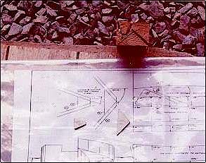
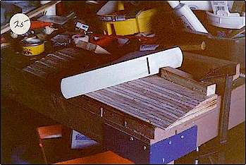
Made the engineering copies at KINKOS. [ ALWAYS use copies in the shop;
originals locked up in the library ]
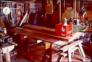
Took initial garage pictures of the pile of supplies . . .
I ll begin the layout either this evening or tomorrow.
Have been giving some thought to cosmetic design modifications; including side
decks for a PT Boat look. Could use 1/8 inch ply.
06/20/97 . . .
 Lofted all of the
parts except the hull bottom; that would have taken an entire sheet by itself. I think
it's too dangerous; too prone to error to have half templates unless the part is that way
- to be butt joined together. Also laid out a template of the sheer, 1 inch wide, for the
gunnels. Lofted all of the
parts except the hull bottom; that would have taken an entire sheet by itself. I think
it's too dangerous; too prone to error to have half templates unless the part is that way
- to be butt joined together. Also laid out a template of the sheer, 1 inch wide, for the
gunnels.
Decided to make templates of all the ½ inch parts. Also to make the
motorboards from scrap ply rather then waste the A-C stuff; may give it a Luan cover .
{will be encapsulated and well above the waterline}
Roughly cut out the parts. Kept all side panels and gunnel pattern on one piece
and put it with the LAUAN. Placed the other shapes on the ½ inch ply for most efficient
cutting.
06/21/97 . . .
Made final placement of rough-cut templates on ½ inch ply. Used spring clamps
to hold in position and cut both together. Used 60 grit disk to smooth out inevitable
glitches .
06/24/97 . . .
 Cut and
sanded the stem templates to size. Laid out the lines on one of the blocks of OAK; both
fit on one block. Put an old hollow-ground, thin kerf planer blade in the saw. Lined up
and made the cuts. WORKED !! [see picture at right] Cut and
sanded the stem templates to size. Laid out the lines on one of the blocks of OAK; both
fit on one block. Put an old hollow-ground, thin kerf planer blade in the saw. Lined up
and made the cuts. WORKED !! [see picture at right]
Next I'll layout and cut the hull bottom. No template; would need full sheet
and be wasteful.
06/25/97 . . .
Supposed to be literally a killer heat day today. A few days ago had a small
quantity ( 1/4 once ) of 5:1 epoxy cook off almost right after mixing. I ll be using a low
ratio hardener for the interior fillets so that presents no problem, however I want to use
high ratio for exterior and sheathing. I have also been giving some thought to using
CARBON POWDER FILLER on the hull and keel bottom; for strength, abrasion, and slickness .
06/27/97 . . .
 Finished
cutting the ply parts. [except the motor boards; I should be able to table saw them from
scrap] Finished
cutting the ply parts. [except the motor boards; I should be able to table saw them from
scrap]
Wanted to cut the gunnels quickly and didn't care if they were rough or not.
Used a much heavier, and courser cutting, blade than I had been using (for the fine
cutting). Found it not only cut faster, but also cleaner and followed the line better.
Used the same technique when I cut out the bottom panel (single, 1/4 inch,
panel). Scored the line first, to minimize splintering.
The weather has been extremely hot the last several days. Have only been
working a few hours a day. Like the winter; only the reason in reverse.
The up side is that the epoxy work should go quickly. The interior work will
use the 2 : 1 slow formulation - 40 minutes @ 77 degrees F will give about 25 minutes @ 90
degrees F.
Cutting the RED CEDAR should be fairly easy. I may even move the table saw
outside, or to the front of the garage.
06/27/97 . . .
The table saw was a bit heavier & bulkier than I remembered; left it where
it was. [generated a LOT of saw dust; next time I WILL move it] Cut the 5/4 x 6's to a bit
more than the length of parts with a hand saw. Then ripped true edges and correct widths
on the table saw. The longest pieces were the keelsons. Left everything over length. Easy
enough to trim to size during actual assembly, and longer is always better than, TOO SHORT
!
The RED CEDAR cut quite nicely. My handsaw is a toolbox length Stanley. The
thin kerf planer blade seemed to pinch and bog down and wander a bit; could be the blade,
or because it wasn't carbide. Switched to the carbide tipped, alternate grind, rip
(combo?) blade. Wider kerf but better cutting. Good for the crosscutting to length as
well.
Started the assembly process, DRY - NO GLUE. A couple of the dimensions seemed
odd, mismatched with no explanation in the text. The inside {bow end} of the box keel is
truncated by the stem. The bottom is very pointy, yet goes inside. The length of the stem
is 3/4 inch shorter than the end of the keel sides it's attached to; line it up with the
top? Bottom edge? Center it?
Reading the text and thinking logically gave an answer. The side panels are
bent around the bottom . . . bottom tapped flush with the lower edge of the side panels .
. . . Marked the length of the lower stem, I'd left that over size, and set a side panel
top front upper edge to it. The 3/4 inch space at the bottom allowed for the thickness of
the bottom and the point to fit through. The extra 1/4 inch space would be filled with the
filleting material. Ditto for the transom end.
Held the side panels in place on the stem with spring clamps and drilled angled
pilot holes through them and into the OAK stem. Drywall screws followed. I ll back them
out and insert thickened epoxy in the space later; then remove them entirely after the
epoxy sets.
Cut the RED CEDAR to size for all the framing and DRY assembled the box keel
transom and upper transom & fastening frame. No thread holding problem with the
OAK. The RED CEDAR requires a bit more care. When working alone, especially with parts
that are held in the splayed out position . . . , a power driver comes in quite handy. Or
have a trained Octopus. However, even using Deep Thread screws, if you set the clutch too
high you'll spin the thread like a drill bit. My units (one battery, one A/C powered),
have SIX settings; my normal or starting point is #2. It's a simple matter to increase it,
or go back and finesse that last millimeter or two by hand.
06/29/97 . . .
Cleaned up the garage. Screwed down the waferboard sheet. Set and leveled the
short horses in place and screwed down cleats to prevent shifting. Mixed up some 5:1 epoxy
and sealed the edges of the bottom panel. After it absorbed for a bit, I semi-nailed [left
the heads a good bit above the surface for easy pulling], and screwed the sides, flush, to
the bottom.
07/01/97 . . .
 Temperature
about 80 degrees F. Decided to work with the 5:1 ratio for the box keel interior seams.
{note: DID NOT epoxy the transom in place - will work from fore-to-aft and align ALL the
transoms last} Used about 3 pumps {about one once per pump set; resin & hardener}, to
start. Had to increase to 5 because added too much WOOD FLOUR; mixture to dry. Went on
nicely but a bit rough surfaced. Not as smooth as I had expected with the Ball Tool . Have
to play with the mixture a bit; add some SILICA and TALC. DON'T want either a ROCK or
MUSH. Temperature
about 80 degrees F. Decided to work with the 5:1 ratio for the box keel interior seams.
{note: DID NOT epoxy the transom in place - will work from fore-to-aft and align ALL the
transoms last} Used about 3 pumps {about one once per pump set; resin & hardener}, to
start. Had to increase to 5 because added too much WOOD FLOUR; mixture to dry. Went on
nicely but a bit rough surfaced. Not as smooth as I had expected with the Ball Tool . Have
to play with the mixture a bit; add some SILICA and TALC. DON'T want either a ROCK or
MUSH.
Made up a couple of mixes ; unthickened mixed in a cup then poured into a
bucket for adding fillers. Worked quickly but not hurriedly. Only seemed to get a little
warm in the bucket. Tongue depressor worked well for initial placement & smoothing.
Ball did better OVER TAPE; could have used a bit heavier fillet - tape & ball would
have evened it out. Made up about 2 pumps of unthickened mixture to completely wet out the
tapes {used 3 inch in forward 1/3rd, most curved area, and 2 inch on rest}.
[when I returned from my interview, about four hours after last brush stroke,
set up strong & dry - after this experience I'll reserve the Very Slow Hardener for
temperatures OVER 90+, and do some time / temperature / hardener-blend experiments]
07/02/97 . . .
Measured and marked one of the Upper Side Panels. Attached the Upper Stem with
SILICA thickened 5:1 epoxy and screws.
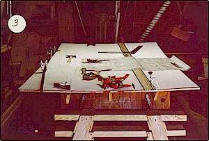
Took pictures.
07/03/97 . . .
Fitted the HULL BOTTOM on - DRY. Secured the bow end to the lower stem with a
drywall screw. Weighed the panel to conform to the curve of the sides. The aft end is
about 1/4 inch short of the ends of the box keel sides, BUT so is the box keel bottom.
Originally thought I had measured wrong but this confirms that the upward curve of the bow
end changes the length overall by this slight amount. My idea, NOT to epoxy the box keel
transom in place paid off. A little trimming of the keel sides is all that is needed.
Removed the keel transom. Unscrewed the transom from the fastening frame ,
applied SILICA thickened 5:1 epoxy and put it together again. Coated all the edges with
unthickened epoxy to seal them. Also coated the internal areas of the box keel where they
would contact; prevent starved joints later.
Disassembled the Upper Transom. Made up a COMBINED epoxy [1/3rd 5:1 and 2/3rd
2:1{the slow formula}, by volume] mixture. Divided the mixture into a cup and a bucket.
Thickened the epoxy in the cup. Reassembled with the SILICA thickened mixture. After
assembly coated all edges and internal surfaces with the unthickened mixture to seal them.
The temperature was above 80 degrees in the garage, and humid. The Styrofoam
cup was a highly compact container and concentrated the volume and any exothermic heat.
Even though it sat for a good bit, as I applied the epoxy and assembled the separate
parts, it didn't t go off .
The time certainly exceeded the 15 minutes of 5:1 open time and I ve had
volumes as small as ½ once go off in 5 minutes at these conditions. The bucket was a
2-1/2 quart translucent plastic mixing container, the bottom about 6 inches in diameter.
The unthickened portion sat undisturbed while I went through the assembly process. There
was no change apparent in the mixture. Possibly a very slight thickening but no
discernible warmth felt on the bottom of the container. Went on easily with a disposable
bristle brush [too thick for a foam one; also wood too rough - would pull off pieces of
rubber foam]. Splashed in a dash of denatured alcohol toward the end to stretch the volume
so I could complete the sealing.
SIX HOURS after finished, Lower Transom well into green stage - dry and well
hardened. Able to use Surform tool to clean up squeeze out without clogging. Upper Transom
surfaces still a bit tacky to the touch. Dry to the touch at EIGHT HOURS; well before the
24 hours of the VERY SLOW formula alone. Good pot life but I d like to shorten the set-up
time; will try a 50:50 mix next.
Removed the screws from the attached Upper Stem / Upper Side Panel. Attached,
DRY, the other side panel. Using spring clamps, braces, and bungee cord, sprung UPPER
SIDES into approximate position on HULL BOTTOM. Also wedged UPPER TRANSOM in place.
Everything seemed to fit together well; side / bottom curves matched.
07/04/97 . . .
Getting to a cost decision point; have already been going over this in my mind
quite a bit. From an engineering and production standpoint, the 6 oz. tight weave on the
bottom and the 4 oz. regular weave on the sides is excellent. From an out of pocket
expenses standpoint, I haven t sold Nymph yet and I have both left over pieces of regular
6 oz. cloth and a full 8 yard length of 72 inch wide 6oz. cloth.
Made up about 2 ounces of 5:1 epoxy. Approximately doubled it's volume by
adding WOOD FLOUR, SILICA, and TALC. Mixed in each in turn to achieve smooth structural
fillet material. Gently added more SILICA at end to get stiffness. Material began to heat
up as I was mixing. Poured it into a 2-½ quart container to spread it out. Applied in
thin tack welds to BOTTOM of hull and box keel sides; about FIVE per side. Made them small
and thin so that when I flip the hull to complete the process they will both hold the
bottom in place and be easily covered and reinforced by the full depth fillet. Used a
tongue depressor as a tool; mixture went on very easily. Finished smooth and with correct
stiffness. Because they are so thin I want as full a cure as practical before proceeding.
NOW I JUST NEED THE PATIENCE TO WAIT TILL TOMORROW !!
NOTE - NOTE - NOTE If the suggested method of using tape to
support the sides doesn't work, I just thought of a way to line up the UPPER HULL
SIDES more securely than with tape, AND give adjustability. Use the hole saw and cut
out 6 to 8, ½ inch ply disks . Drill a pilot hole in them off-center. Screws inserted
from the outside, these would be inside, against the side and able to rotate against the
inside of the bottom to align the sides flush with the outside of the bottom. They would
be attached to scrap cross pieces or shorter pieces secured to the center portion of the
bottom where the foot well will be. After the sides are filleted into place the support
structure would be removed and the holes filled.
07/05/97 . . .
Couldn't wait; had to peek last evening. Had set up well.
With Jo's help, flipped the hull over and placed a padded 3rd sawhorse at the
center of the bottom curve. From the hardness of the tack welds today, last evening was
probably the green stage .
Made up a batch of combined epoxy; about 70-30;. 6:1 to 2:1 [FAST - hard ,
highly water impermeable to VERY SLOW - softer & flexible , less water impermeable].
Added WOOD FLOUR, TALC, & SILICA fillers; smooth and stiff structural fillet - applied
very well. The ball tool may make a deeper fillet but it is messy; and wasteful if you use
the tape-and-tear technique. The tongue depressor is simple but has a different curve
radius and makes a shallower fillet. I just may go back to making my own filleting
paddles, with a 9/16 inch radius, and use the 1 inch ball tool to set the cloth tape into
the wet fillet. Or make up my own special tool.
Applied the material to hull and bottom / box keel side juncture, the screw
holes, the box keel bottom / side gaps, and the imperfections and knots. Even though I
will be glassing this area I would rather use a structural than a cosmetic filler
material.
I'll give everything about two hours @ 80 degrees F, then take a peek. If I can
catch it at the green stage the clean up will be easier.
1600 hrs
Set up nicely. Now at initial green stage ; cuts with Surform tool, but a
little bit gummy . Rather than wait it out went ahead and did the initial clean up work;
the keel box bottom, splatters & drips , and the big chunks. Easily cleaned out the
Surform tool with a wire brush.
07/06/97 . . .
Hard & Dry . Residue popped out of mixing bucket; even as thin film. The
odd chunk left on the hull & keel shaved off with the Surform tool. Used the random
orbit sander {w/ 60 grit} for smoothing & truing of keel edge; also dust removal.
Later I ll run the router around the keel bottom; a 1/4 inch round over bit, the bearing
against the bottom should give the truest edge. The width of the hull bottom, out from the
keel side, is shorter than the height of the sawhorses [ as I originally considered], so I
can rotate the whole assembly on its side for better router control.
07/09/97 . . .
TOO HOT !! Temp 85 degrees, but feels dripping wet.
Have been debating with myself on which order to do the next steps. Put on a
seal coat of 6:1 epoxy. Used an old fuzzy roller; just get it on quickly, the raw wood
would absorb it to level the surface. Mixed up 7 ounces, toward the end another 3 ounces.
Even though I worked quickly, the roller was starting to feel distinctly warm at the end.
The seal coat should allow me to use 6:1 for the cloth wet-out coat; thin ,
quick, and the better water barrier. Then I ll have the option of adding some SLOW to the
filler coat. Then 6:1 again for the cover coat.
When this seal coat is set I ll see how the 72 inch material drapes. If it does
then I'll do the entire bottom in one shot. If it doesn t hang well, I ll do it in
segments; the BOTTOMS first, then the keel sides. Rather than use tape I just overlap the
edges at the seams.
On the up side about it being hot; even thin coats set up fast. The KEEL BOTTOM
has glossy spots and dull areas ; typical of the absorption rate for FIR PLY. In this case
it can be ignored. The 72 inch, 6 oz. cloth draped well. [started with 4 yards; used
a bit more than two]. Went from one edge, smoothed and tucked into joint, then over keel
and same on other side. Leaving an inch or two overhang on both sides, trimmed off about a
foot from one side. Cut a dart at bow to allow smooth lay.
The trimmed length will a) cover one upper side completely, b) cover both upper
sides half-way, or c) be put away. The plans say nothing about any glass sheathing. The
only mention is for taping the exterior bottom edge of the KEEL and the interior HULL
BOTTOM / KEEL SIDES joint where it's accessible [because this instruction comes after the
assembly and cut out of the bottom opening over the box keel]. It also mentions that, . .
. if the bottom panel is allowed to flex, the (box keel sides) will crack . . . . My
approach covers the entire bottom, keel bottom / keel side joint, keel side, keel side /
hull bottom joint, and hull bottom. This is in addition to interior taping. Note that all
of the plans concern is for the lower structures. It even seems as if a paragraph was
skipped in the assembly process for permanently securing the upper sides. They only say, .
. . stick in place with duct tape or some other way . Then they go into detail about the
gunnels. After assembly, and before getting involved with the gunnels, the sides must be
considered in regard to sheathing. From bottom to sheer would take the whole full length
piece. I could split it and cover the half the side from the sheer down, or the bottom up.
Or I could just use 3 inch tape at the bottom edge and not sheath the upper sides. [NOTE;
the 440 lb.. waterline seems to be 3 inches up from the bottom center]
Either way, I'm electing to sheath the bottom now because it's easier to move a
segment than the whole boat; I don't have to worry about drips especially if the sides
aren't sheathed; and the glassed edges will integrate better with the internal side
fillets.
07/10/97 . . .
VERY COOL this morning; almost chilly. Good time to do the bottom epoxy job,
but had an interview. Good circumstance to note though.
Temperature in the low 80's and about 77 in the garage. Plus a breeze and low
humidity. Began epoxy job about 1300 hrs.
Lined an old cookie sheet {a shallow tray} with aluminum foil; about 10 x 15.
Shallower and more surface area than a paint tray. Mixed up 14 oz of the 6:1 formula.
Poured some down the middle of the keel and spread it with a squeegee. The rest went into
the tray. Some difficulty in achieving wet-out [would be easier in sections; do a quick
roll down of some epoxy down the center then unroll the cloth into it] but don t want to
take a chance and float the cloth. Some of the problem could be related to the amount of
cloth and it's ballooning . Using squeegee, 3 inch foam roller, and slotted roller got the
job done. Working, from center out the first batch was enough for the keel bottom, sides,
and about a roller width out on the hull bottom. Two more 7 oz batches completed the job.
I let the epoxy be the time guide .
A little bit of residue that was left in the mixing bucket, after pouring out
the first batch, eventually began to heat up and gel {I had gone for it after using up
what was in the tray}. However, nothing that was poured into the tray went off . To be on
the safe side I did change roller covers after the first batch was used up. A bristle
brush was used to help in the joints and other dry areas. I flushed it every so often with
DENATURED ALCOHOL.
Finished about 1500 hrs. Everything went well; epoxy still wet . Now just has
to cook.
07/11/97 . . .
 WELL DONE
this morning. A few bubbles , and dry spots at the edges but good on the whole. A bit of
an amine blush feel, but light and solid enough to move outside for washing and sanding,
if necessary. I'll also sheath the transoms. Possibly give the KEEL & HULL BOTTOMS a
filler coat. The KEEL SIDES later; when I can rotate the hull so they are in a horizontal
plane. WELL DONE
this morning. A few bubbles , and dry spots at the edges but good on the whole. A bit of
an amine blush feel, but light and solid enough to move outside for washing and sanding,
if necessary. I'll also sheath the transoms. Possibly give the KEEL & HULL BOTTOMS a
filler coat. The KEEL SIDES later; when I can rotate the hull so they are in a horizontal
plane.
ACTUALLY gave filler coat to ENTIRE BOTTOM. The mixture was stiff enough not to
drip. If there are any sags, they ll go into the KEEL/BOTTOM joint, which I may be
cosmetic filleting anyway. Mixture a bit too thick, or maybe my squeegee technique, a good
bit of weave still showing. Used two batches of 7 ounces each; with Q-CELL, TALC, SILICA,
and MILLED FIBER fillers. If I really want to get dedicated about it, I ll sand it down
and roll on a final coat of only slightly thickened - with milled fibers - epoxy; maybe
the hull bottom & keel sides.
Finished @ 1500 hrs
1700 hrs - coating not completely set
2000 hrs - coating set; gave a few passes with Surform tool to knock down the big chunks .
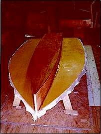
07/12/97 . . .
Examined job and took pictures this morning. Well sealed but not perfect; could
probably let paint coat smooth it out, but don't want to count on it. I ll sand it down,
then take a more careful look.
07/13/97 . . .
The MILLED FIBERS disappeared in the epoxy solution; could be why some call it
liquid glass . A slight gelling was the only apparent effect. The other fillers gave body
and some coloration; the stiffness from the SILICA. The advantage is that vertical
surfaces can be done. The disadvantage is difficulty of filling in the weave; requires a
thicker initial application and skilled squeegee work. NEXT TIME go with a bit more MILLED
FIBERS and maybe a bit of Q-CELL and ROLL it on horizontal surfaces with a fuzzy cover. If
impatient {guilty as charged} then after roll on, add additional stiffeners and apply with
squeegee to vertical areas.
07/15/97 . . .
Rough sanded the bottom with 60 grit and Random Orbit sander. Did it outside
and with vacuum attached to minimize epoxy dust. Not perfect, but suitable prep for either
another coat of resin, or paint primer. After sanding rinsed off with water & rag, and
allowed to dry completely. Moved bottom assembly back into garage.
07/16/97 . . .
With the on-going heat-wave outside work is minimal. Took advantage of the
heating of the day. Sheathed the BOX KEEL and HULL TRANSOMS with cloth scraps . Needed
about 4 ounces of resin. Finished before noon. Intended to catch it after initial green
stage and trim scraps square, but set-up solid by about 1500 hrs. Used Surform tool to
file overlaid edges; rough but fairly flat and suitable for a fill coat of resin. Will
rough sand before application.
Sanded down the sealed and unattached side of the UPPER STEM. Because the stems
were made over-length, when I had attached this stem to the starboard UPPER SIDE. I forgot
to leave a 1/4 inch space at the bottom for the HULL BOTTOM panel to fit into [for flush
fit]. {this is not mentioned in the plan instructions, but I figured it out from the
dimensional differences on the LOWER STEM & BOX KEEL SIDE assembly} I was able to
simply correct this, or it could be considered a method of fine fitting, by a few strokes
with the hand saw on the stem.
07/17/97 . . .
Kept going over in my mind different methods of cutting the 5-1/2 degree and
6-1/2 degree bevels on the UPPER TRANSOM. Different mechanizations to fit it on the short
topped table saw; alignment jigs to use a circular saw, etc. Finally decided to go with
the KISS principle first, if it didn't work, then worry about it.
 Using a
single woodworkers clamp, attached it to the end of the workbench. Marked the bevels with
the bevel square [and added these angles to the bevel board] and used the Surform file and
block plane. A few minutes of sweat {it's still hot} and it was done. When starting from
the RED CEDAR side use the Surform tool first; it cuts quickly so be careful. When
starting from the PLYWOOD side use the block plane first; the ply acts like end grain and
the Surform tool chatters a bit. Using a
single woodworkers clamp, attached it to the end of the workbench. Marked the bevels with
the bevel square [and added these angles to the bevel board] and used the Surform file and
block plane. A few minutes of sweat {it's still hot} and it was done. When starting from
the RED CEDAR side use the Surform tool first; it cuts quickly so be careful. When
starting from the PLYWOOD side use the block plane first; the ply acts like end grain and
the Surform tool chatters a bit.
A bit of edge sanding, I had rough trimmed the epoxied cloth, and a good
surface sanding then it was decision time again for the next step. Even though I was
impatient to continue with the assembly process, logic told me it was intrinsically better
to apply the fill coat on a horizontal surface. I also wanted to try another dispensing
experiment.
I keep two sets of containers going. One set is a quart of resin and a ½ pint
of hardener with 5:1 ratio pumps installed. This gives me about 30cc of mix ; about 5cc
more than one ounce. The other set is the gallon and ½ gallon containers the epoxy
arrived in. With ketchup pumps installed, putting out about one ounce per pump , this
gives seven ounces of mix at a 6:1 ratio. Good for the bigger jobs like the bottom, but it
would be nice to be able to quickly get medium quantities without the complexity of using
measuring containers.
Gudgeon Brothers, the WEST SYSTEM people, put out a quarterly tips &
techniques magazine called Epoxyworks.
From this I have gotten several methods of producing small quantities of mix . One method
is a stop [it looks a bit like a shoe, with two heights ], to limit the stroke of the
resin & hardener pumps while maintaining the same ratio. I have two; 50% and 25%.
I measured the stroke length of the ketchup pumps at 3 inches. THREE pumps of
resin + ONE-HALF pump of hardener = 3.5 ounces of mix at a 6:1 ratio. A 1-1/2 inch stop is
all that's needed.
To prove the theory I made up a 3.5 ounce batch and thickened it a bit with
Q-CELL, TALC, and SILICA. Poured it on to the sanded transoms, spread it with a squeegee,
then tipped it off with a disposable foam brush. Did it in the sun; I wanted it to set-up
quickly. Went on well; surface tension kept it on the surface rather than running down the
sides. The brush being loaded with the mix, it started to go off as I finished {about 1300
hrs}, so the mix ratio must be good.
1600 hrs - Set up solid, thick, flat, and smooth. A few minor holidays , but
that's why I used Q-CELL and TALC; it will be sanded and painted. Gives me a good idea of
how the bottom will turn out. Some white blotching . Won't matter because entire boat will
be painted; next time use just Q-CELL, and maybe some colorant if desired.
07/18/97 . . .
Fitted the BOX KEEL TRANSOM into place with WOOD FLOUR mix. Used the covered
over screw holes; inserted 3 inch Drywall screws part way as handles for insertion and
adjustment. Used edge of paint stir stick as alignment tool. When the interior of the box
keel is cut out I can fillet if necessary.
Let it set for about four hours. Removed the 3 inch screws and using the same
holes, attached ½ inch plywood scrap braces with 1-1/4 inch Drywall screws. [used shorter
screws because I wanted to snug them up tight without going all the way through the frame]
Using spring clamps, held the UPPER TRANSOM in place against the braces until screws could
be set. Again because I wanted to snug up the transom, made the pilot holes in the bracket
oversize.
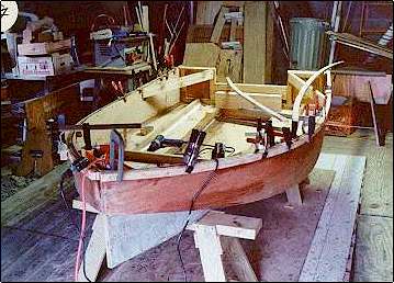
Set the UPPER SIDES, attached to the UPPER STEM [only ONE SIDE epoxied in
place; other attached with 1 inch screws] in place for a trial fit . Started from the stem
end; used woodworkers clamps to hold aft ends to transom frame. I admit, the trial fit is
only a partial reason; you get a great deal of satisfaction from just looking when it
really begins to look like a boat.
07/19/97 . . .
Tapped down UPPER STEM to assure good contact & position, then examined the
fit of the UPPER SIDES.
Sides about ½ inch short at transom end; thickness of plywood. Some due to
cutting BOTTOM PANEL outside the line , some because panels not stretched into position.
Because the BOX KEEL TRANSOM is secured into position, I can t take the easy way out; trim
the box keel & bottom panel by ½ inch and reposition the upper transom. Anyway, a
stressed skin should give more rigidity.
Removed the 1-1/4 inch screws, in the UPPER TRANSOM braces, and replaced them
with 2 inch screws and ½ inch spacers [the spacers prevent the screws from penetrating
the frame when snugged down]. Also added two more screw holes in the braces. Backed out
the screws attaching the UPPER TRANSOM to the braces, but NOT COMPLETELY. Allowed the
transom to move forward. Loosened the clamps holding the SIDE PANELS to the transom,
repositioned the side panels, and attached them to the frame with 1 inch or 1-1/4 inch
screws; depending on the holding power needed. NOW, by carefully and evenly drawing up the
longer bracing screws, I slowly pulled the transom into position under tension.
Cut to exact size and trimmed to shape the interior beams & braces I had
previously prepared. Some of them were temporarily installed. These, along with pieces of
½ inch PVC pipe and spring clamps, and other long clamps, plumbed the sides 90 degrees
relative to the BOTTOM PANEL. At the bow, between the stems and on the epoxy attached
side, and at three other sites along each UPPER SIDE PANEL where the bottom edge of the
side and the bottom would stay flush with very little pressure, I placed strips of masking
tape on the exterior seam. These were spots where I would place epoxy spot welds and the
tape was so the filleting material wouldn't drain through. The unepoxied side of the stem
and the upper transom are NOT epoxied in place at this time.
Mixed up about 2 ounces of 5:1 and brushed some on the marked sites. This is to
prevent an epoxy starved joint, because the wood was raw and to get some fluid down into
the seam itself. Made a stiff paste with the remainder and WOOD FLOUR, plus a bit of
SILICA for smoothness, and applied as a shallow fillet.
The mixture set in about two hours. It was hard to the touch but when I used
the Surform tool on a sample it was still a bit gummy . Initial green stage so I ll not
remove any tensioning screws or stress the hull. Did remove the masking tape to check for
any leakage ; mixture was just right and no trimming was needed.
07/21/97 . . .
The assembly instructions say to, Tap the bottom panel flush with the bottom
edge of the upper sides . . . This is ASSUMING that the cutting of that edge was
absolutely perfect . And that it is a perfectly fair curve. I m NOT that good. However,
physics and the materials are. When laying out the box keel sides, points were plotted
then connected {with the batten} to form a spline curve . Theoretically all that is
required are two end points and a center point. Even if it was then cut out VERY ROUGHLY,
it has defined ends and a center point. During assembly, when the BOTTOM PANEL was laid
over the keel and WEIGHTED TO CONFORM TO THE CURVE, it defined the spline curve like the
batten !! With this in mind, proved by running my fingers lightly along the bottom edge
and sighting along it as well, I let the bottom panel be the guide. This may leave a step
or ledge at the exterior UPPER SIDE/HULL BOTTOM seam. This presents no real problem. This
area has to be rounded off prior to finishing and/or the application of a reinforcing
glass tape. A relatively easy sanding filler can be roughly applied at that time.
Removed the temporary stem brace and the screws holding the unepoxied upper
side panel. This allowed the panel to swing free of the stem. Masking taped the exterior
seam from the first weld back toward the transom; stopped about a 12 inches FORWARD of the
transom. [NOT fastened this area will allow the side to be easily sprung out for the final
fitting of the bottom panel & transom] Taped the other side from this point all the
way to the stem. Prepared about 1 ounce of 5:1 epoxy and lightly painted the side of the
stem, the opposing area of the side panel, and the interior upper side/bottom seam. Made a
WOOD FLOUR/SILICA paste with the remainder, applied it to the stem side and refastened the
side panel with waxed screws. Wiped off the excess paste, then taped the area from
the stem back to the previously applied tape.
Mixed up a 7 ounce batch of 6:1. Added about 1.5 ounces of MILLED FIBER {glass}
for structural strength. As I was mixing, the mass started to exotherm {heat itself up} so
I added a 3 ounce batch of the SLOW mix. Added a bit more MILLED FIBER and continued
mixing. There is a noticeable color shift and the consistency becomes jelly-like.
Now blended in WOOD FLOUR and SILICA for bulk, smoothness, and stiffness.
Because the mass was greater, and still in the bucket , it begin to exotherm again. At
this point I quickly, and only a little neatly, spread the mixture along the prepared
interior seams.
Once spread out there is more time to work the fillet. Using a ½ inch + radius
tool, a fillet deep enough to cover the spot welds was made. Working smoothly and with a
light touch, the fillet wasn't pulled apart [the milled fiber looks like a powder when
dry, but it is fine individual threads and adds to the cohesiveness of the mixture], or
forced through the seam. The edges of the fillet were cleaned up as much as possible, to
minimize later sanding of the very tough material.
The last touch was at 1300 hrs. FOUR hours later the fillet was hard. Began to
knock off the high spots and odd chunks. The Surform tool scrapings were dry indicating
that the initial green stage had passed.
Removed the holding screws in the stem.
07/24/97 . . .
Big change in the weather; rain & drizzle, and 60 degrees F in the garage -
a drop of about 30 degrees.
Checked the drawings for positions of the KEELSONS and TRANSVERSE BEAM.
Outlined their locations on the interior of the bottom panel. Will use these to position
the pieces later. Beveled to approximate fit. Marked centerline points on transom.
Removed the screws at the lower edge of the UPPER TRANSOM. Made a couple of
passes through the bottom seam with the hand saw to trim the BOTTOM PANEL edges. Marked
the interior edges of the transom on the side and bottom panels. Removed the transom
braces and the transom. Sprung the side panels and, with sandpaper and plane, trimmed the
bottom panel so it would allow the side panels to lay evenly on the transom. Made up 3.5
ounces of 6:1 epoxy. Painted the marked areas where the transom would sit with unthickened
epoxy. Mixed the remainder with SILICA to a thixotropic cream; a thick adhesive, not
fillet mix. Applied a somewhat thick layer to the wetted area and set the transom in
place. Using waxed screws, secured the transom in place. Tightened screws gently, watching
for an even squeeze out . Used a few additional screws as necessary. Wiped off or
repositioned excess epoxy/silica cream. Tried to be as neat as possible; the silica will
make for very hard sanding once it sets up.
With the lower temperatures, it will probably take a bit more time to reach the
green stage than the last few days. However, I ll check in two-hour stages.
07/25/97 . . .
Because of the rain, and laziness, didn't bother to check set-up times. By next
morning it was well past the initial stage. Took a little more muscle with the Surform
tool. The last bits will be taken care of by the prep work prior to painting.
Rounded the tops of the KEELSONS with a ½ inch CARBIDE roundover bit Beveled
the TRANSVERSE BEAM to fit.
Marked the forward line for the keel cut out. Attached a short straight scrap
for the router to bear against. Used a ½ inch CARBIDE roundover bit with a lead bearing;
partially exposed. Make sure the cutters go up the shaft or it will rub and burn. Made a
couple of entrance holes in the waste area, on each side of the centerline - left a center
attachment tab for support. Adjusted the depth of the bit to the amount of roundness
desired and cut out the bottom panel over the box keel. Worked like a charm; the bearing
followed the LOWER sides, the router base plate followed the scrap forward and the
interior transom aft, and the edge is also nicely rounded for attachment of glass tape.
Looked at the drawing and re-read the instructions for the dimensions on the
forward beam that supports the fore edge of the thwart. I want to avoid cutting a full 5/4
x 6 x 8ft for a 38 inch piece, if I can. The piece is indicated as 2-1/2 inches wide, yet
the seat support portion bearing on the bottom panel is only ½ inch thick, to level the
thwart . Used a 5/4 x 1-1/4 inch scrap and straight edge - seemed level enough. [ intend
to attach the thwart with screws, the top of the forward support will be accessible for
any planing required.] Cut a 5/4 x 1-1/4 inch scrap to size and beveled the ends to fit;
side panel-to-side panel and rounded to the fillets. Marked the location of the box keel
cutout on the underside of the beam , cut another scrap to fit. Outlined the location of
the beam on the bottom panel.
Drove small wire nails into spots on the KEELSONS and box keel cutout scrap .
Cut the heads off to leave short anti-slip points.
[temperature 80 degrees] Mixed up a 9.5 ounce batch (1/3 fast; 2/3 slow) of
epoxy. Painted the bottoms of the beams and keelsons, also the outlined areas. Added
MILLED FIBERS, WOOD FLOUR, and SILICA to form a structural / adhesive paste. Applied the
paste to the KEELSONS, eased into place and tapped down to set the points. Applied the
paste to the TRANSVERSE BEAM and tapped it into position across the ends of the keelsons.
Glued the parts of the forward beam together. Applied the paste to the beam and tapped it
into place; the lower portion in the box keel.
07/26/97 . . .
I had used less WOOD FLOUR than in previous fillets, also a higher percentage
of the slow epoxy. When I examined the set up fillets they had a glassy appearance. I will
be doing some remaining filleting with only the slow epoxy to see which has the greater
effect.
The drawings call out for ½ inch teak or mahogany for the gunnels. The written
instructions rescind this because it won t bend in two planes at once. If my idea works,
Plywood or Pine are more in line with my wallet.
I laid down the gunnel template on the remainder of the ½ inch ply sheet,
holding it in place with spring clamps. The idea was to use this to guide the router. The
1 inch narrow strip is very flexible and rather delicate - it deflects a great deal. Tried
using one of the 1/4 inch ply strips I had cut out when cutting the template; nailing it
down in several places. Still too much deflection - the router exerts a good deal of
pressure against it's guide . Cut out a sample - a great deal of wander and slippage made
gouged edges. Would probably need nails every few inches.
The sample fit and was flexible enough to be bent into place on the upper edge
of the sides.
Went back to the template and laid out THREE outlines. With a coarse blade ( 7
teeth per inch ) in a saber saw, cut out the entire section containing the outlines. [with
the curve and waste space between outlines, the full space is a bit over 10 inches - would
require a ½ x 12 x 8ft plank per side; rather expensive even in cheap pine] Laid that
section on top of the ply sheet and held it in place with SCREWS. Using the saber saw, cut
out the gunnels a pair at a time. Removed the screws, stacked all six together, and used 3
inch screws to hold them together. Now the bottoms can be planed & smoothed
simultaneously and squarely. {the tops will be worked on after their in place on the boat,
along with the top of the sides}
It takes a bit more time than just cutting strips of 1/4 inch ply on a table
saw, but no more time if you are using a saber saw. In addition it allows the use of ½
inch material as originally called for; less actual cutting than using 1/4 inch ply to
achieve the same thickness, and you don t have to split the aft end.
07/25/97 . . .
{another hot and humid one; have to work carefully}
In an ideal situation I'd have a shop and a tool for everything like Norm
Abram. However this is reality; an open garage, a stone back drive, and I have what tools
I have.
The most efficient tool for shaping the stacked gunnels would be a power plane.
Another good tool would be a belt sander w/36 grit belt. [has multiple uses & will be
my next purchase, when I can afford one] I have neither, but I do have a 4-1/2 inch angle
grinder with a 50 grit sanding disk. It makes a LOT of fine dust so I moved it outside;
one end clamped to a sawhorse. Did the job.
Separated the gunnel strips. NOTE: when I screwed the strips together, used the
power driver to pull the strips tight and pulled the screw heads a good bit below the
surface of the top strip. Didn't think anything of it at the time. Now the screws can't
back out. Badly cracked it getting the screws out. I ll have to make another. Next time
use a washer or buffer piece.
For efficient use of material, all the strips face the same way; A side out for
only ONE side of the boat. Flipped three strips around so the would fit the sheer. Sorted
through them so that the worst outside face would be the first strip against the side; the
best on last.
I knew a single strip would bend and fit; with typical impatience tried to see
if I could do it with all three at once. Spring clamps held them in place, but they
cracked as the sheer curve increased at the bow. They have to be fit singly.
Prepared a 3 ounce batch of SLOW epoxy. Painted the sheers and the contact
surfaces of two gunnel strips. Mixed MILLED FIBER and SILICA into the remaining epoxy,
which was starting to warm up. Transferred the mix to a larger container. Brushed the
heavy cream mixture onto one of cracked gunnel strips. Positioned it in place on the sheer
with spring clamps - WORKING FROM THE BOW and leaving overhang at the stern. Using a scrap
block for alignment, squared up the bow and put in a clamping screw. Working from the bow,
aligned gunnel and put in clamping screws with backing blocks. At the point of the gunnel
crack, an exterior and interior backing block was used to draw the area flush.
NOTE: The instructions seem to skip the process of filleting the sides into
place. It calls out for duct tape or some other temporary fastening in the step before
attaching the gunnels. The sideways force required to bend the strips moved the entire
boat; no way would an adhesive tape have held. Read and use logic at all times.
Applied the rest of the adhesive to the other gunnel strip and set it in place
on the other sheer. Because the strips were all slightly twisted in one direction this
strip didn't quite fall into place. Two mechanical clamps were needed in the bow area;
applied after the clamping screws.
The instructions don't mention it, but the gunnels should be applied in sets -
one Port and one Starboard. Especially if you are using ½ inch material. It exerts a lot
of pressure and this way it's balanced. The pressure also has the effect of straightening
or smoothing the plane curve of the sides and a definite feeling of increased stiffness.
{LOOKS GOOD, TOO !!}
07/28/97 . . .
 Checked
the boat this morning. My practice is to remove the residue from the plastic containers
and examine it's condition as a check of what's happening at the glue joint . In this
case, using only the VERY SLOW (2:1) epoxy, the material peeled out in one piece like
plastic from a mold. Surface hard, but soft and very flexible. The lower ratio mixes are
supposed to be somewhat more flexible than the high ratio, but I didn't expect this much.
I ll leave it on the bench and check again in the afternoon. Checked
the boat this morning. My practice is to remove the residue from the plastic containers
and examine it's condition as a check of what's happening at the glue joint . In this
case, using only the VERY SLOW (2:1) epoxy, the material peeled out in one piece like
plastic from a mold. Surface hard, but soft and very flexible. The lower ratio mixes are
supposed to be somewhat more flexible than the high ratio, but I didn't expect this much.
I ll leave it on the bench and check again in the afternoon.
07/29/97 . . .
Decided to wait until this morning; about 24 hours cure time. Somewhat harder
to the touch but still flexible. It was rigid enough to pop an edge from a smaller &
thinner plastic container so I could peel it out. Yesterday it was flexible enough to move
with the container so that it couldn't be removed. Nice surface but want a bit more
stiffness in most of my seams, joints, and underbody surfaces. Would use only high ratio
where abrasion resistance is required; for example, on the edges of the keel cut-out where
the sides of the MOVABLE SEAT will bear.
Mixed up 1.5 ounces of 5:1 epoxy. Prepared the mating surfaces of the QUARTER
KNEE FLANGES and interior side. Made & applied a structural fillet / adhesive mix and
temporarily secured the parts with screws.
1600 hrs - The fillet material has set up well; residue in cup hard and came
out in large pieces. Removed the holding screws. Set flange flush with top of sheer.
Should need only minimal shaping.
Temporarily set the second gunnel in position with spring clamps. Stood at
the garage door and just looked at it. It's hard to put into words the satisfaction
this gives me. I don't know if it's because I m out of work and it gives me a sense of
achievement, or I think of the things my father has made, some not so functional.
07/30/97 . . .
Prepared a batch of STRUCTURAL fillet material using 6.5 ounces of a 50-50 mix
of fast 6:1 and slow 2:1. Applied a deep fillet to the skipped areas of the sides, and the
transom bottom & side seams.
Prepared a 9.5 ounce (1/3rd fast, 2/3rd slow) batch of COSMETIC fillet
material; adding some MILLED FIBER for cohesiveness and TALC for smoothness. Bulked it up
a great deal with Q-CELL before adding a small amount of SILICA to prevent sagging.
Applied this to the bottom edges of the KEELSONS and TRANSVERSE BEAM. Also the forward
edge of the forward seat support.
Mixed up a 1 ounce batch of 5:1 and added a bit of MILLED FIBER. Applied this
to the edges of the keel cut-out. Placed strips of 3 inch glass tape along the sides edges
from the aft corner to the forward seat support. Made up a further 2 ounces with MILLED
FIBER added. Most of this was used to fill in the weave up to the transverse beam; this is
the area where the MOVABLE SEAT will ride. The rest was used to wet-out & lightly fill
the tape which will be covered by the forward thwart; this for additional flex prevention.
1630 hours - Checked the residues I'd left in the sun. The structural material
was hard & pieces could be chipped off. The cosmetic material was surface hard but
flexible and fingernail dentable; chunks could be peeled off. When I checked the fillets
in the shade of the garage, the cosmetic ones were still soft and tacky to the touch. It's
been about 3 hours @ about 80 degrees. I used the slow to give me working time with the
material, as the batch was rather large and the mixing time prolonged. Looks like 50% slow
is about the limit for normal days.
2200 hours - Checked again. Looks like cake frosting but set up solid; both
residue and boat.
This basically finishes the interior epoxy work. The only thing left is the
securing of the foredeck support beam; that will be after the gunnels go on and will only
use an ounce.
07/31/97 . . .
Relatively cool yesterday and last night. Same for this morning. Fits well with
my intentions to use the 6:1 hard formulation; I want as much stiffness in the gunnels as
possible. {Garage temperature about 75 degrees.}
Mixed up 3.5 ounces and immediately added a bit of MILLED FIBER, then SILICA to
a paste state. Applied the paste to a gunnel strip for one side, and the attached gunnel
on the other; not concerned with epoxy starvation here. Set the strip in position using
spring clamps, then used screws to draw it tight. In certain difficult spots used bar
clamps. The paste is thick and gave a good indication of contact by squeeze out; wiped off
the excess.
I had spread the paste on the attached gunnel to distribute the mass and give
me more working time. I was going to need it for this side; I intended to use the cracked
& broken gunnel strip. {by using it as the middle piece, sandwiched in with epoxy, it
would neither look nor behave and any differently than a solid piece} Lined up and
attached the short bow piece; held it in place with a screw into the stem. As I bent it
around, by the other end and not the middle, it cracked again. Using the epoxy paste, a
piece of plastic bag, a long screw and a couple of blocks of wood, I pulled it into place
with an overlay and a backing block. Applied the paste to the broken ends, pushed them
together and used the same overlay and block technique to secure it to the sheer. Worked
my way back to the stern, setting spring clamps about every 8-12 inches. Then went back
and set the screws from bow to stern. Again used hard clamps in a few places.
The paste stayed workable the entire time. Even after I was done there was some
left over and no exotherm. Used a squeegee and applied that little bit to the tape along
the box keel cut out.
Depending on the temperature and the timing, I may even be able to set the last
pair of the gunnel strips in place this afternoon.
08/02/97 . . .
Had some difficulty with the last mixed bit of epoxy curing. Based on residue
and squeeze out, the material stayed rubbery and didn't seem to go beyond that state. With
the knowledge that it will finally cure, it's simply a matter of time and holding it in
place, I attached the last pair of gunnel strips. [during the process, under about the
same conditions, I came to the conclusion that the problem was due to overconfidence; too
little physical mixing, stirring, before adding fillers] I made up a 3.5 ounce batch of
6:1 {poured a bit on to the rubbery residue}. Added MILLED FIBER and SILICA to a paste. It
started to exotherm a bit at the end of the process so I spread it on a tin foil covered
cookie sheet. [the problem mix did not; my first clue that something was wrong, and I
ignored it] Lined up the bow end, set a screw half-way in, and worked my way aft; applying
adhesive mix, spring clamps, and screws. Then I started on the other side. By the time I
worked my way half way down the side the mixture had gelled beyond the point of
workability. I made another batch, using about 1 ounce of 5:1 solution. Completed the
side.
Mixed a bit of WOOD FLOUR into the remainder. Used the stiffer mixture, and a
couple of screw points, to hold and fillet the FORWARD DECK BEAM into place without
causing a hard spot .
NOTE: by the afternoon the residues, the fillets, and the squeeze out have
cured solid. The small bit poured on the rubbery residue acted as a catalyst and the
entire mass has cured. the only difference is the time I spent stirring the epoxy fluids
(@ 75 degrees) before I began adding the fillers. I had simply gotten complacent about how
easily the fluids mixed, with their decreased viscosity when the temperatures were in the
80's & 90's. BE WARNED and TAKE NOTE!
Completed laminated gunnels look good. A number of voids in the plies are
visible, as expected from A-C ply, but easily filled by any number of materials, depending
on finish. However, the technique is proven. Could be used with finer grade of ply (no
voids; more expensive), or solid woods (no voids; much more expensive; Teak & Mahogany
VERY expensive).
Except for screw hole patching, this should finish the interior epoxy work.
Assembling and setting the motor boards into position, and filling & taping the chines
are all that's needed on the exterior. Because I'll be using Styrofoam peanuts for
flotation, the quarterknees and foredeck will be attached with RTV and Stainless screws.
Then it's finish prep time !! (which includes assembling the seat and thwart)
08/03/97 . . .
Easy day today. It seemed a waste to make all the layers of the motor mount the
same 8 inches x 24 inches, then beveling the stack. I made a simple scale drawing and cut
the segments; this minimized both the waste and the beveling effort {cut them square , too
much of a risk to hold them vertically on the saw}. Spring-clamped them together, dry,
with one edge square the other stair-stepped. Drilled pilot holes for registration &
clamping screws and marked edge lines. Made up 3.5 ounces of 6:1 and added MILLED FIBER
and SILICA to create a structural adhesive paste. Applied it to the contact surfaces with
the moderate sawtooth edge of a spreader. Used edge marks to line up steps and cinched
down waxed clamping screws. Looked for moderate squeeze out.
08/04/97 . . .
Removed screws. Because I made sure they didn't go all the way through and
flipped the last board, the aft surface won't need any filling. My calculations to set
this up indicate that a line drawn, on the side, from a point 3 inches down on the short
top piece, from the top edge to the bottom piece, the bottom edge will give the bevel
line. Hand plane, power plane, belt sander, etc.; take your choice. When beveled, it will
be set into place with epoxy and screws. Later the screws will be replaced with Stainless
thru-bolts. The shims will be cut to fit.
08/05/97 . . .
A little time with a hand jack plane and the beveling was done. [here is where
buying tools at the right price pays off ; I've had this Stanley 14 inch plane, still in
the box, for years. I paid less than $20 for it from a mail order close out.]
Theoretically this could have been done with a block plane but it would have been a LONG
JOB. The plies made a decent guide; keep them relatively parallel as you cut. Use a SHARP
cutter. It's also nice to have a stable bench made from an old door and a piece of cheap
Luan ply; you have no qualms about putting a screw into it to stop something from sliding.
Also used the plane to even up the top surface of the gunnels & sheer.
08/06/97 . . .
Held the motor mount in place on the transom and marked it's location. Drilled
three pilot holes through the mount and set waxed screws in place. Used the points to mark
the transom and drilled starting holes. Made sure that these locations would be in the
thicker section of the mount and into the 5/4 inch frame. {later, these screws would be
replaced with suitable thru-bolts & washers}
Made up a 3.5 ounce batch of 6:1 epoxy. Painted the beveled surface of the
motor mount; there's a lot of raw edge surface and a high probability of absorption. Added
some MILLED FIBER and sufficient SILICA to make a thick STRUCTURAL adhesive. Spread it on
the beveled surface with the coarse tooth edge of the squeegee. Lined up the protruding
points of the screws with the locating holes and cinched it into place. Used the squeeze
out to create a small fillet on the top and side edges.
Mixed a bit of WOOD FLOUR with the remainder and set a scrap piece of OAK into
the open V at the bow end of the gunnel strips. The drawing shows the gunnels being
rounded off and flush with the LOWER and UPPER STEM points. With this modification the
ledge created by the gunnel will go all around.
Made up another 3.5 ounce of 6:1 material. To this Q-CELL was added with some
TALC for smoothness. Then sufficient SILICA was added to create a stiff paste. The screw
holes in the motor mount were filled, also the other screw holes in the interior and the
gunnels. Then the voids and hollows in the gunnels were overfilled .
When everything has set-up I ll turn the hull over and glass the exterior SIDE
/ BOTTOM seam.
08/07/97 . . .
Using 3.5 ounces of 6:1 as a base, added TALC and Q-CELL to a thick paste. Then
added SILICA to form a loose putty. Slathered this on the edge seam and filled any
depressions. When set, it will be planed flat on the bottom as a base for the router and a
round over bit.
08/08/97 . . .
Planed flush with Surform tool and cut roundover with router. Used sander &
file at point of bow and end of box keel. Mixed 3.5 ounce batch of 6:1 and prepared bottom
& all transom edges. Set 3 inch tape into position along sides, from stern to bow,
then starting about the middle rolled upper half over onto bottom. Added dabs of
unthickened epoxy and firmly rolled down with slotted roller. Mixed up another 3.5 ounce
batch of 6:1. Did the same with exposed transom edges, only cut 3 inch tape in half for
1.5 inch strips. Added a bit of MILLED FIBER to remaining epoxy and brushed it onto taped
side seams.
Read again the comments on MICROTRAWLER in Bolger's book. In discussing the
drumming of the bottom at speed, and the keelsons, stated, The half-scale model {Bee}
which proved the concept started to come unstuck due to vibration in her sponson bottoms
after jumping some steep waves; longitudinal stiffeners cured the trouble within reason
and were carried over into the bigger boat. The comments on Bee's drawings indicate that
it was the sides of the box keel that started to crack. With the entire bottom sheathed in
a single width of 6 ounce cloth, the interior box keel seams structurally filleted and
taped, and the bottom taped to the sides, this boat is not about to come apart.
This should end the epoxy work. Just in time, too; I'm almost out of resin and
it would be a problem getting more shipped - there's a UPS strike on.
Finished by 1300 hrs. By late this afternoon everything should be set-up. I'll
try to do any planing or Surform work in the shade of the garage, then it's outside for
the major sanding.
08/09/97 . . .
Everything set up fine.
Trimmed the Oak piece inserted at the bow of the gunnel.
Tried to Surform the underside of the gunnels. Was able to break off the drips
of epoxy, however the plywood laminate proved a bit more difficult. Experienced the same
problem as with the beveling of the motor mount; chattering and rough going. Actually
knocked the boat off the saw horses with the force it took. Have an idea about using the
4-1/2 inch grinder but I don t want to create that much heavy dust in the garage.
09/01/97 . . .
Rain - on and off - and various interviews [dead end] interrupted the smooth
schedule.
Found a source for the KUTZALL wood cutting disk; however at $35 not
appropriate for me.
Took one of the 24 grit super heavy backed, pre-holed 7 inch sanding disks and
cut out a 4-1/2 inch disk. Using the grinding disk backer and nut, installed on right
angle grinder. Cut like a champ!! Went through the gunnel laminate with ease. Wore goggles
and mask - a LOT of dust. Need to be VERY CAREFUL - the narrow edge can easily cut right
through the 1/4 inch plywood skin. After doing all the work, the disk didn't even look
used.
The disk I used seem to be resin coated. I had gotten them in a large box of
various types & sizes of paper at a marine tent sale a number of years ago; at a dirt
cheap price. I have since found that these are available in 4 and 4-1/2 inch sizes. Also a
rubber backing plate was available. Haven't gotten any at this point. The heavy duty disks
don't seem to need any backing plate, at least for flat work; the 60 grit and finer
probably do.
After cleaning up the underside of the gunnels, I filled the voids in the ply.
After allowing about 48 hours for drying I rolled on the first primer coat - alkyd based.
After drying and spot sanding I applied alkyd filler to the cloth tape edges to ease the
edge transition. When this had dried well a good overall sanding was done.
09/12/97 . . .
With interviews {fruitless}, on and off weather, and several of Joanne's
projects there has been some delay. HOWEVER, I applied the second primer coat and it has
withstood several days of both rain & sun with no adverse effects. In addition, the
interior has been well sanded and the first coat of primer applied. This time a bit of
thinner was added to help flow and absorption; the ply really soaks it up. I used 90% of a
quart for two coats on the exterior {epoxy coated} and so far about 75% of a quart for ONE
coat on the interior.
Before priming I fitted the foredeck and quarter knees . I ll have to fill the
gunnel on one side to get the deck to fit flush. Good chance to try some of the plastic
fibers - the UPS strike is over.
Cut out the Luan for the seat & thwart. Assembled the sliding seat , a bit
shorter than specified, and gave it a coat of Bombay Mahogany stain/urethane. Really dark
red. Recommends two coats, but I think this is more than dark enough. A couple of cover
coats of varnish should do. I ll probably do the same with the thwart. The foredeck and
knees I just varnish.
I've got the RED that Joanne picked for the exterior; hopefully a quart will be
enough. I ll have her pick a beige-tone for the interior as well.
09/19/97 . . .
Joanne picked a beige she liked, with a hint of red. I got another quart of the
Evermore alkyd primer. Needed at least half of it to finish the second interior coat. So
far I ve used about 2-1/2 quarts, total.
When I fitted the foredeck I gouged the edge of the Luan and the gunnel due to
the gap between the two. In addition the Luan was a piece together job. Laid out the
pieces on a piece of heavy plastic sheeting, over a piece of heavy ply. Measured and cut
out a Dutchman to fix the gouged area. Used some scraps of glass cloth and epoxy to put
all the pieces together and tacked the pieces down to the ply to keep the alignment. This
morning - tight, solid, and one piece stiff. I ll re-fit it later today.
I'll also give a good sanding to the interior. Depending on the timing I may
also do the first coat of interior finish paint. Tactically any drips of the light color
could be covered by the heavy exterior color. Also, with the boat turned bottom up for
exterior painting any drips wouldn't get on the interior.
10/09/97 . . .
Fitted the foredeck. Stained with the Bombay Mahogany. Wiped it, and gave
another varnish/stain coat. Not as dark as the sliding seat but enough to mask the
Dutchman . Gave three coats of Spar Varnish. Used up the last of the old stuff. Will buff
down and wax to protect the screw heads anyway. Filled & leveled the gunnel area with
alkyd filler; dries quickly and sands easily.
Also stained and wiped the rowing thwart. A decidedly lighter tone than the
foredeck. Probably the best tone. Tried it on the quarterknees as well. Gave all
pieces three coats of the varnish.
The accidental water staining of the quarterknees gave me the incentive to test
the Luan ply. A simple test; I tossed a long scrap upright in a bucket of water. Left it
for several days; taking it out occasionally and twisting & bending it. NO SEPARATION.
Let it dry out - still no separation.
Thinned the interior paint with a bit of Penitrol and gave it the first coat.
Dried smooth and glossy. good coverage. Couldn't wait any longer; flipped the boat,
sanded and gave the exterior two coats of RED. To quote Joanne, That is definitely Arrest
Me Red !! Will probably need a third coat to completely blank out dark spots revealed by
sanding. [Jim, at Home Depot said that's why he hated painting red - coverage was always
tough.]
10/12/97 . . .
Left it to dry while we were at the Annapolis Sailboat Show. The weather has
turned a bit cooler so there was still a few soft spots . Turned right side up and laid
out the topside portions. Great difference in tone on the quarterknees. Also the gunnels
don t look good light toned. Moved back into the garage; I'll wipe some of the Bombay
Mahogany stain on the quarterknees and gunnels
After treating the quarterknees, decided to try the lighter interior color on
the gunnels. Gave them a second coat. Looked good when completely & evenly covered;
leave it this color.
10/16/97 . . .
Cut, sanded, & lightly stained the flotation enclosing panels .
The written specifications call for a TOTAL of 1.5 Cubic Feet of flotation
(combining fore & aft spaces). The drawing calls out, 30 lbs. buoyancy under , for
each location. I calculated 0.83 cu.ft. under each quarterknee, and 1.66 cu.ft. under the
foredeck for a total of 3.3 cubic feet
The specification says, . . . if the whole space is completely filled . . . . I
interpreted that to mean from the DECK LEVEL to HULL LEVEL. Bolger may mean from
deck level to bottom of deck beams -- 3-1/2 inches.
If we calculate 2 pound foam then we have approximately 60 lbs./ cu.ft. or 198
pounds of buoyancy; more than twice as much as specified. My personal choice - I d rather
have it than the open storage spaces fore and aft.
10/19/97 . . .
With all the parts laid in place she looks great.
Fill the flotation compartments, screw down the covers , a quick third coat of
red, and she's done.
10/30/97 . . .
All that is left now is a bit of red touch-up (3rd coat on topside only).
Not counting the dreaming time it only took FOUR and a HALF MONTHS !!
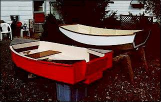
|
