“Start to Finish”
Part II
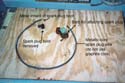
I was not particularly pleased to see one leg
of the three-legged puller moving up out of the hole it was
supposedly threaded into. It meant the puller was going to be
almost useless in removing the flywheel..
Some people have heard that one can pound on the
crankshaft (sticking up through the flywheel) to remove the
flywheel, but is that true? Not if you are going to just pound
away without thinking about what you are attempting to accomplish.
The crankshaft is tapered, and the bore of the
flywheel has a matching taper. In order for the hammer to be
of any help, the crankshaft needs to be able to move down, out
of the flywheel bore. How does one provide this “travel.”
Well. it might be possible for someone to suspend the outboard
by it’s flywheel, so that the crankshaft (and the rest
of the outboard) can move downward when the crankshaft is hit.
A more practical approach is to use the crankshaft
“end play.” If you grasp the flywheel of an outboard
and lift, you will find that it will move up and down a few
thousands of an inch- this movement is termed “end play”
and it is necessary for the crankshaft to have this “slack”
so as not to bind-up when running. If one lifts up on the flywheel
prior to smacking the crankshaft, the crankshaft is free to
move downward that few thousands of an inch. Not very much travel,
but it can be enough.
A few caveats: DON”t hammer directly on
the crankshaft, and make sure that you are lifting just the
flywheel and not the whole magneto.
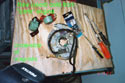
I left the otherwise-useless puller in place,
and smacked the puller with the hammer(instead of the crankshaft
itself) while lifting up the flywheel by levering it with a
big screwdriver. I also heated the flywheel with an ordinary
hardware store propane torch. Penetrating oil can also be applied
and allowed to soak, but I found it unnecessary. The heated
flywheel popped loose after only a few smacks.
Again, I will point out that if you damage your
engine’s crankshaft while hammering on it, you have reduced
your engine to “junk’ status.
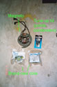
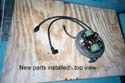
With the flywheel removed, I set about replacing
the cracked coils and also the points, condensers, and spark
plug wires. The coils I installed were some that I salvaged
from a “parts engine” that someone had given me,
so my cost in them was nothing. In fact, one can almost say
I was paid to take them, as this parts engine, an early ‘60s
Evinrude 10 hp, was equipped with a fuel pump that Jim Michalak
wanted so that he could convert his “pressure tank”
’56 Johnson 10 to use ordinary outboard fuel tanks. In
exchange for the pump and related hardware, Jim gave me his
two pressure tanks (his other motors all use pumps, as well.)
So this “free engine” I was given provided me with
the coils and also a pressure tank to use on the 5 ½
hp project motor.
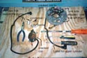
The magneto is removed from the engine by backing-off
4 screws, two of which pass through the coil heels and the other
two pass through just the magneto plate. A clip can be removed
from the bell crank attached to the magneto to disconnect the
throttle linkage. Unless there are wires for a shut-done switch
still to disconnect, you can lift the magneto off the engine
and set it on the workbench.
I installed new metallic-core sparkplug wires on the “used
but good” coils. One simply cuts a piece of this wire
(which can be bought by the foot) to the same length as the
old wire, and pushes it onto the coil’s barbed connector
Once the coil is attached to the magneto plate and the wire
routed underneath, the spark plug boot from the old wire can
be installed on the new wire. When the rubber boot is pulled
off an old wire, one can easily see the inner metal connector
which is simply “stabbed” into the end of the wire.
I never take a chance on 50-year-old sparkplug
wires; I always replace them.
The coils have laminated metal “heels”
which are in close proximity to the magnets in the rim of the
spinning flywheel. This is how the electric current is produced.
It is important that the “gap” between the coil
heels and the flywheel magnets be correct; too much gap and
the spark is weak; too little gap and the flywheel hits the
heels. The heel gap is set by making sure the surfaces of the
heels are flush with a machined surface on the mounting bosses.
You can feel this by running your fingers over the heel and
the mounting surface. Also, once the flywheel is reinstalled
(not now) be sure to rotate it slowly by hand to check for any
interference.
It should be noted that the coil mounting holes
are not “slotted” to allow adjustment; the small
amount of room present in the round holes is enough to make
this adjustment
I also always replace the “points”
and “condensers”; they are dirt cheap and readily
available. Since there are two of everything (one set for each
cylinder) I suggest that the novice do one "side”
at a time, leaving the other side intact to act as a three-dimensional
parts diagram. The point gap cannot be set until the magneto
has been reinstalled on the engine.
With new points, condensers, sparkplug wires,
and sparkplugs, one has a virtually new ignition system, retaining
only the flywheel magnets and the cam that actuates the points.
If you are lucky and your engine has already had new coils installed,
you can almost always use those coils.
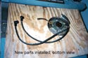
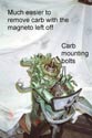
Once I had all the new pieces installed on the
magneto, I set it aside rather than reinstall it on the engine,
as it is easier to remove the carburetor with the mag off, although
certainly not necessary. I would not remove the mag just to
work on the carb.
The carb is held on with two nuts, but there are
usually knobs and such to remove-the newer the engine, the more
complicated the knobs. Take good notes as to how these are installed
and put them in a secure place. I usually just cut the fuel
hose to the carb, as I always replace the hoses. The hoses on
the 5 ½ were probably original and were so brittle they
broke-off. On a fuel-pump equipped engine, you will have a hose
going from the quick connector to the fuel pump, and another
hose from the fuel pump to the carb. On some of the bigger old
OMC engines, you might also have a hose supplying the pressure-vacuum
pulses to the fuel pump, rather than the pump being mounted
directly to the source of the pulses.
A pressure tank motor will have a short fuel line
running from the quick connector to the carb, with a second
hose (supplying pressure to the pressure tank) running from
the quick connector to the intake manifold.
One may also have to disconnect some of the linkage
that connects the carb to the magneto. This is almost always
a system of levers and bell cranks and pushrods. The less you
take apart, the better; keep careful notes and DON’T LOSE
THE PIECES!
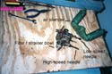
With the hoses and linkage off, remove the carb
from the engine and find a halfway clean (it won’t stay
that way) place to clean and rebuild it. You are going to need
a carb rebuild kit and a can of spray carb cleaner. In the interest
of safety, you will also need chemical safety goggles and maybe
some rubber gloves.
Next time, we will "operate” on the
carb.
Later