“Start to Finish”
Part III
Sierra Marine
is the company that sells after-market replacement parts for marine
engines. One of the types of items that they sell is carburetor
rebuild kits. I have used many of their kits with few
problems, and one nice thing that many of their kits contain is
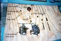
a set of instructions with drawings. I purchased a Sierra kit
for the Johnson
Taking the carb apart is no big deal (neither is putting it back
together.) Unscrew the high and low speed needles along with their
packing nuts, then remove the 5 or so screws which hold the bowl
on. Once the bottom of the bowl is removed, the cork float can
be removed by pushing out it’s hinge pin. Don’t allow
carb cleaner to get on the cork float, as the float is varnished,
and carb cleaner removes varnish. Most OMC carbs will also have
a brass “nozzle” running up vertically through the
center of the carb’s upper half. Remove and blow it out
with the spray carb cleaner, and take note of the “doughnut”
seal (usually cork) which sits on the nozzle.
You will need a very-wide blade screwdriver to remove the float
valve seat from the upper half of the carb. If you strip it’s
little slots with the wrong size screwdriver, getting the old
seat out may be a chore. You might want to invest in a good screwdriver
of the proper size for this chore. Note the seal under the seat.
At this point, the carb is “tore down” as much as
I usually dissasemble it.
The kit will probably contain some tiny welch plugs (like small
freeze plugs) and the instructions may say to remove the old welch
plugs from the body of the carb in order to clean the passages
behind them. Installing the new welch plugs can be a big hassle
and I almost never remove the old ones if they are showing no
signs of leakage.
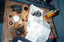
Your can of spray carb cleaner should have come with a tiny plastic
tube for spraying into tight places. Put on your safety goggles
and install the tube in the can’s nozzle and find a place
where dripping flammable cleaner will not be a hazard. Spray the
cleaner into each and every opening and passage on the carb. Keep
in mind that as you shoot cleaner into one passage, it may come
shooting out of another passage aimed directly at your face. Keep
cleaning until you think your have gotten rid of any crud and
the passages appear clean.
In the “old days,” it was usually recommended that
one soak the carb in a container of carb cleaner. I used to do
that, but for the last few years I have just sprayed them out
with the spray cleaner and have had no problems.
Note; there is “packing” in the openings that the
high and low speed needles screw into. The packing nuts (threaded
tubes) that install over the needles tighten down on tiny rings
of a sealant material in order to prevent leakage around the needles.
As new packing is supplied in the kit, the best thing to do is
remove the old packing prior to cleaning. That can be easier said
than done, and I usually just leave the old stuff in there, and
add a new ring or two of packing on top when reinstalling the
needles and packing nuts. Be mindful that if the old packing becomes
dislodged and stuck in the needle’s seat, your engine will
not run correctly.
After the carb appears clean, install the new needle seat and
seal, and reinstall that brass vertical nozzle and it’s
new “doughnut” seal. You can install the new bowl
needle along with the old float (assuming the old float is not
in too bad of condition, and most that I see are not). Note that
the kit usually contains a tiny wire “hair pin” that
connects the float needle to the float arm, so that the needle
is pulled open by the weight of the float and not just by it’s
own weight.
You can now install the bottom of the bowl back onto the carb
body, using the new gasket from the kit. Place a new ring or two
of packing in the openings for the high and low speed needles
and install the needles themselves. Your manual will tell you
how many turns from closed the needles need to be set at when
trying to start the engine but I never look. I usually try around
¾ to 1 turn open on both needles and play it by “ear.”
when trying to start the engine. Install the packing nuts but
keep in mind that you may need to remove one or both to get the
carb air silencer back on.
Bolt the carb back on the engine using a new gasket; note that
these carb kits fit several different engines and you may have
a choice of 2 or 3 gaskets - choose the one that matches-up to
your old gasket.
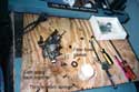
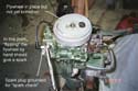
After bolting the Johnson’s carb back on, I cut and fitted
new fuel hoses and hose clamps. I also installed a small “in-line”
fuel filter in the hose. This engine has a fuel strainer/filter
bowl on the carb; other OMC’s have a remote-mounted strainer/filter
bowl somewhere on the power head. Be sure to clean the strainer
element and bowl, and the carb kit should contain a new gasket
for the bowl. I like to add the in-line filter as a “belt
and suspenders” approach to protecting my newly-rebuilt
carb.
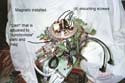
With the carb back on the engine and all “hooked-up,”
I reinstalled the magneto. As I set it down on it’s mount,
I was careful to avoid bending the rubbing block arms of the points
on their cam; the arms on the points are spring-loaded and one
has to manually pull them back or they will hang up on the cam
that actuates them, when installing the magneto. Run the spark
plug wires to the back of the engine. Make sure the big sheet
metal “cam” that most of these engines use to operate
the carb butterfly linkage is in the front of the engine and not
“hung-up” on anything. Once you are sure the magneto
is correctly in place, put in the four screws which hold it in
place and reconnect the linkage arm to the vertical shaft that
comes up from the twist-grip throttle control.
Next, I checked and set the carb-to-magneto sychronization, which
is not as complicated as it sounds. A manual, such as the
one that I reviewed for Duckworks, will show you
how to do this, but on old OMC’s all that is involved is
lining up the carb linkage with certain marks on the engine.
At this point, you can manually rotate the crankshaft until the
keyway is aligned with the rubbing block on one set of points
and set the gap on that set to .020. Then rotate the crankshaft
until the rubbing block on the other set of points is aligned
with the key way and adjust that set of points to .020. Setting
the point gap on the Johnson took all of about 5 minutes.
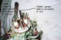
Set the flywheel down on the crankshaft, making sure the key is
properly seated. At this point, you can clamp a spark plug to
a good ground on the engine with a pair of Vice Grips, and by
flipping the flywheel by hand, check for spark on both spark plug
wires.
Make sure that there is no interference between the flywheel
and any part of the magneto, and the engine “flips’
easier if you leave the sparkplugs out.
If the spark appears to be good, install the flywheel nut and
torque it down to the specs given in the factory service bulletin
posted in the “Magnetos”
column. After the nut is torqued, check for interference again.
If you do not know for a fact that the waterpump impeller is only
one or two years old, I strongly suggest that you install a new
one. I always do. Although many of the large old OMC engines have
a little access panel on the motor “leg” that one
can use to disconnect the shift linkage, the little 5 ½
does not have one. In order to change the water pump impeller,
which is located in the lower unit, on the 5 ½, one must
remove the power head first. The older engines, such as the ’55,
are a bit easier to deal with because they do not have a “pan”
under the power head, so the screws are a bit easier to get to,
but it is not that big of a chore to remove the power head of
any 5 ½. On the little Johnson, about 5 minutes had all
the screws out and the power head ready to lift off, but I noticed
that none of the screws was really “torqued-down”
very tightly - it appeared that the power head had been removed
in the not too distant past. To avoid having to disconnect the
new fuel hose that I just installed, I unscrewed the fuel quick
connect fitting from the engine, rather than disconnecting the
hose from the fitting.
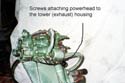
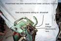
Before actually lifting the power head off of a 5 ½ (or
an old 7 ½ for that matter), be aware that there is some
“hardware” sitting on top of the driveshaft that you
do not want to lose track of; have the outboard vertical (tilted
all the way down) and carefully lift the power head off. Remaining
on the driveshaft will be the seal for the lower end of the crankshaft,
consisting of a ring resting on a pin driven through the driveshaft;
a spring, and a seal thingy sitting on top, and there is another
part or two in the mess. Carefully remove these pieces which are
simply sitting on the driveshaft, and keep notes as to the order
in which they are reinstalled.
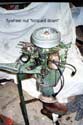
With the power head off, you can now disconnect the shift linkage
from the shift lever, and then unbolt and remove the lower unit.
Next time we will replace the pump impeller, and deal with a
surprise problem.
Later
Max
|